If you do not have a model already loaded to the COMSOL Desktop environment, select File >
Open to select an MPH file from your file system or select a file from the Application Libraries. Note that, in the Application Libraries, the files in the
Applications folders are ready-to-use applications. All other files in the Application Libraries contain a model and documentation, but not an application user interface.
Once the model is loaded, click the Application Builder button on the ribbon
Home tab. This will take you to the Application Builder workspace.
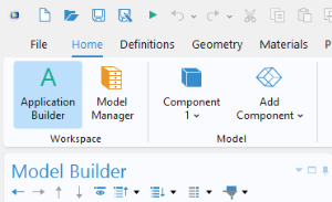
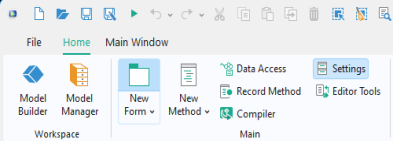
To start working on the user interface layout, click the New Form button in the
Home tab. This will launch the Form Wizard.
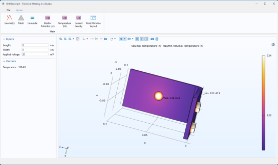
For this example, you can load the busbar.mph model from the Application Libraries at
COMSOL Multiphysics >
Multiphysics. This is one of the models used in the
Introduction to COMSOL Multiphysics manual.
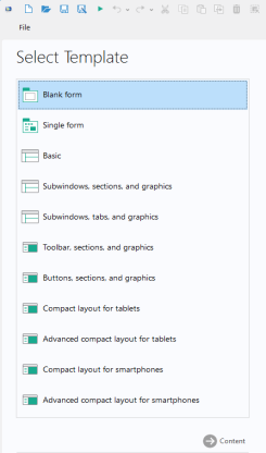
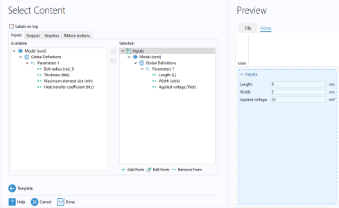
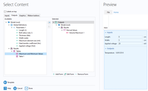
Select the Basic layout template and click
Content. The
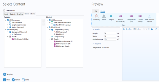
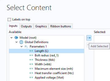
Select Content page has four tabs:
Double-click a node or click the Add Selected 
button to move a node from the
Available area to the
Selected area. The selected nodes will become form objects in the application and a preview of the form will be shown in the
Preview area to the right.
The Inputs and
Outputs tab display the model tree nodes that can serve as an input field, data display object, checkbox, or combo box. Input fields added by the wizard will be accompanied by a text label and a unit, when applicable. You can make other parts of the model available for input and output by using
Data Access (see
Data Access in the Form Editor). Checkbox and combo-box objects are, for example, only available in this way. For example, you can make the
Predefined combo box for
Element Size under the
Mesh node available in the wizard by enabling it with the
Data Access feature.
In the figure below, three parameters, including Length,
Width, and
Applied voltage, have been selected to serve as input fields.
In the figure below, a Derived Values node representing the maximum temperature has been selected from the
Outputs tab to act as a data display object. Note that the temperature value shown is a placeholder intended solely to demonstrate the formatting, not an actual computed temperature.
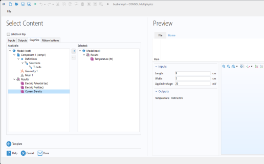
The Graphics tab displays the model tree nodes that can serve as graphics objects:
Geometry,
Selection,
Mesh, and
Results. In the figure below, a
Temperature plot node has been selected. When using the
Basic layout template, this selection determines the default plot shown when the app is started.
The Ribbon buttons tab displays the model and application tree nodes that can be run by clicking a button in the ribbon in the application user interface. Examples of such tree nodes are
Plot Geometry,
Plot Mesh,
Compute Study, and each of the different plot groups under
Results. In addition, you can add buttons for
GUI Commands,
Forms, and
Methods. Note that in this example no
Forms or
Methods are available yet.
The Reset Window Layout option is available under
GUI Commands >
Main Window Commands >
Reset Window Layout. The application consists of two subwindows, one for the inputs and outputs and one for the graphics. The
Reset Window Layout button will reset the two subwindows in the application to their original size. The
Subwindows templates are similar to the
Basic template but additionally enable you to detach, move around, and dock the subwindows. In this case, the
Reset Window Layout operation will rearrange all subwindows to their original position and size.
Click Done to exit the wizard. This automatically takes you to the Form Editor.
To save an application, from the File menu, select
File >
Save As. Browse to a folder where you have write permissions, and save the file in the MPH-file format. The MPH file contains all of the information about the application, including information about the embedded model created with the Model Builder.