Global Definitions — Parameters and Thermodynamics
Start by importing a set of global parameters defining the process conditions for the distillation column, including the operational conditions, feed flow rate and separation specifications.
Parameters
1
2
3
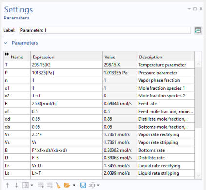
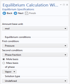
Browse to the file distillation_column_parameters.txt in the following application library folder on your computer, Chemical_Reaction_Engineering_Module\Thermodynamics. Double-click to add or click Open.
Note: The location of a file is based on the installation. For example, if the installation is on your hard drive, the file path might be similar to C:\Program Files\COMSOL\COMSOL64\Multiphysics\applications\.
The parameters defined in the file are added to the Parameters table.
Now define a thermodynamic system including the available chemical species.
Thermodynamics
1
This starts the Thermodynamic System Wizard. In the first step you specify the available phase or phases. You can choose among the following systems:
Gas
Liquid
Vapor–liquid
Vapor–liquid–liquid
Liquid–liquid
2
3
Click Next  to proceed to the next step, adding species.
4
You can use the Species filter field to search among the available species in the database by either Name, CAS number or Formula.
5
Click Add Selected .
6
7
8
Click Next .
This takes you to the final step of the Thermodynamic System Wizard, selecting the models used to compute for thermodynamic and transport properties. For more information on how to choose the thermodynamic model see Selecting the Right Thermodynamic Model in the Chemical Reaction Engineering Module User’s Guide.
9
Select the Advanced options checkbox for detailed control of all models for thermodynamic and transport properties.
10
Click Finish  to create the Thermodynamic System and end the wizard.
The Settings window now displays the package details. The NRTL model requires three sets of binary interaction parameters as well as randomness parameters. Expand the Binary Interaction Parameters section in order to inspect or edit the interaction parameters needed.
Now add an Equilibrium Calculation node to generate an xy diagram for the ethanol–water system at 1 atm pressure.
Note that a thermodynamic system node has been added under Thermodynamics. It is named Vapor–Liquid System 1 reflecting the phases included.
Vapor–Liquid System 1 (pp1)
1
This starts the Equilibrium Calculation Wizard.
2
3
Click Next .
4
Specify the equilibrium conditions. It is possible to create different equilibrium diagrams such as T-x, h-x, P-x, x-y, and so on using two equilibrium conditions. These available conditions are: Temperature, Pressure, Phase fraction, Enthalpy, Entropy, Energy, Density, and Volume.
5
6
7
Click Next  to go to the Equilibrium Function Overview.
8
The Equilibrium Calculation Settings window now displays the set of functions included in the feature. Scroll down in the list and click to select Flash1_1_PhaseComposition_Vapor_ethanol in the Functions list. The name of the function is seen in the Name field. Copy (Ctrl+C) the entire function name to use it below.
Use an Analytic  function to change the composition arguments from moles to mole fractions.
Analytic 1 (an1)
1
2
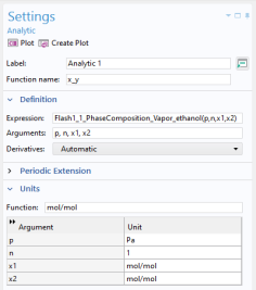
In the Settings window for Analytic , type x_y in the Function name text field.
3
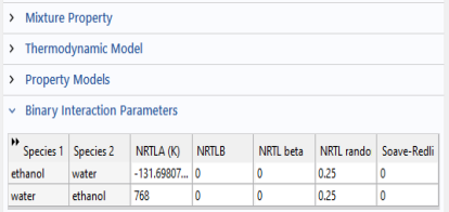
Locate the Definition section. In the Expression text field, type Flash1_1_PhaseComposition_Vapor_ethanol(p,n,x1,x2).
4
Remember to use the same order of the argument as defined in the Equilibrium Calculation node.
5
In the Function text field, type mol/mol. Enter the following into the Arguments table:
Pa, 1, mol/mol, mol/mol.