|
1
|
|
3
|
In the Width text field, type r_p (parameter name for pipe radius).
|
|
4
|
In the Height text field, type l_p (parameter name for pipe length).
|
|
3
|
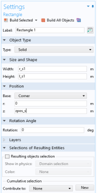
In the Width text field, type r_c (parameter name for chamber radius).
|
|
4
|
In the Height text field, type l_c (parameter name for chamber length).
|
|
5
|
Locate the Position section. In the z text field, type zpos_c (chamber position along the pipe).
|
|
3
|
|
4
|
|
3
|
|
4
|
|
5
|
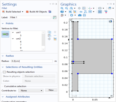
In the Radius text field, type 0.3[cm].
|