|
3
|
|
4
|
|
5
|
|
6
|
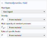
From the γ list, choose From material.
|
|
4
|
Locate the Heat Conduction, Porous Matrix section. From the ks list, choose User defined. From the list, choose Diagonal.
|
|
5
|
|
3
|
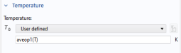
In the T text field, type T_gas_in. This parameter was previously defined in Parameters: Temperature and Monolith Parameters.
|
|
2
|
|
4
|
|
4
|
|
4
|
|
4
|
|
6
|
|
7
|
|
6
|
|
7
|
|
3
|
From the γ list, choose From material.
|
|
3
|
|
4
|
Locate the Heat Conduction, Porous Matrix section. From the kb list, choose User defined. In the associated text field, type 0.1.
|
|
5
|
Locate the Thermodynamics, Porous Matrix section. From the ρb list, choose User defined. In the associated text field, type 0.63[g/cm^3].
|
|
6
|