Transport of Diluted Species in Porous Media Interface
During the Generate Space-Dependent Model procedure several feature nodes were added along with the new physics interfaces. Now go through these features one by one and enter settings, and make sure that they are assigned to the proper domains and boundaries in the geometry.
1
2
3
The fluid will be modeled as compressible. This setting is available in the Laminar Flow interface. This means that the mass conservation equation should be of the conservative form. Choose this form from the Advanced Settings section in the mass transfer interface’s settings window.
1
2
3
4
5
Porous Medium
In the Model Builder window, expand the Transport of Diluted Species in Porous Media node.
Fluid
The mass transport model for the monolith channels assumes that there is only diffusive mass transport in the axial direction of the reactor, here along the z-axis. This can be accomplished by specifying the diffusivity only in the first element of the diagonal diffusion matrix. This may be difficult to converge though, and a more robust alternative is to set the radial diffusivity to a very low value.
1
2
3
4
For each species, change from Isotropic to Diagonal, for the Fluid diffusion coefficient.
5
6
Specify the DF,cH2O matrix as
7
8
Specify the DF,cNH3 matrix as
9
10
Specify the DF,cNO matrix as
11
12
Specify the DF,cNO2 matrix as
13
14
Specify the DF,cO2 matrix as
The entered expressions were set up by the Generate Material wizard and they can be found under the Global Definitions > Materials > Gas: Nitrogen node. D11 represents the zz-component in the diffusivity matrix.
Porous Matrix 1
The porosity is by default defined by the Porous Material node.
Initial Values 1
This model is highly nonlinear due to the reaction kinetics. In this case, starting from a nonreacting system leads to a more robust simulation. To achieve this set the initial concentration to zero.
In addition to the default feature nodes, the nodes Reactions 1, Inflow 1 and Outflow 1 were also added during the Generate Space-Dependent Model procedure. The Reaction feature gets input from the first Chemistry interface in the component. The inflow and outflow features’ icons are marked with the warning sign in the Model Builder window. The warning message, seen when placing the mouse pointer on top of the icons, reveals that they are empty and need to be assigned to the proper domains and boundaries in the geometry.
Reactions SCR
1
2
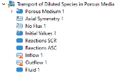
In the Settings window for Reactions, type Reactions SCR in the Label text field.
3
Reactions ASC
1
2
In the Settings window for Reactions, type Reactions ASC in the Label text field.
3
4
5
6
Inflow 1
1
2
3
4
Locate the Concentration section. In the c0,cH2O text field, type cH2O_in.
5
In the c0,cNH3 text field, type cNH3_in.
6
In the c0,cNO text field, type cNO_in.
7
In the c0,cNO2 text field, type cNO2_in.
8
In the c0,cO2 text field, type cO2_in.
Outflow 1
1
2
3
Fluid 1
Next, add a Fluid feature to model the mass transfer in the free-flowing domain between the two catalysts. Use the diffusion coefficients defined by the nitrogen material.
1
2
3
4
5
From the DcH2O list, choose Diffusion coefficient, water in nitrogen (solvent) 5.
6
From the DcNH3 list, choose Diffusion coefficient, ammonia in nitrogen (solvent) 1.
7
From the DcNO list, choose Diffusion coefficient, nitrogen oxide in nitrogen (solvent) 2.
8
From the DcNO2 list, choose Diffusion coefficient, no2 in nitrogen (solvent) 3.
9
From the DcO2 list, choose Diffusion coefficient, oxygen in nitrogen (solvent) 4.