Materials
The next step is to specify material properties for the model. Ready-to-use materials can be selected from the available libraries or generated from Thermodynamics. In this model, first generate a material node for nitrogen (solvent) from our Gas System, under Thermodynamics. After that, generate the solid monolith material. Both these materials are then used to create a Porous Material.
The created materials are assigned to the relevant selections in the geometry. This allows the physics interfaces in these selections to access the material properties.
Generate Material
1
2
This opens the Generate Material wizard which consists of several steps to create a Material node from our property package.
3
4
5
6
7
8
9
10
11
12
13
Gas: Nitrogen Solvent
1
Gas: ammonia(0)-nitrogen(1)-nitrogen oxide(0)-oxygen(0)- water(0) .
2
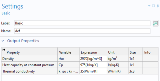
In the Settings window, change the Label to Gas: Nitrogen Solvent, to use a simpler name.
Next, create a user-defined material and associate it with the solid monolith material.
Solid: Monolith Material
1
2
3
4
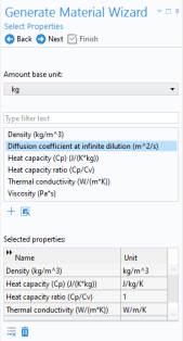
In the Physical Quantity dialog, type density in the text field and click Filter . Select Density (kg/m^3). Click OK.
5
Perform the same action for the properties heat capacity (choose Heat capacity at constant pressure (J/(kg·K)) and thermal conductivity (choose Thermal conductivity (W/(m·K)).
6
Add expressions to the Output Properties section. Type 2970[kg/m^3] for the density, 975[J/kg/K] for the heat capacity, and 35[W/m/K] for the thermal conductivity.
7
In the Model Builder window, select the Material 1 and type Solid: Monolith Material in the Label field to name it accordingly.
In the next stage of the modeling process, add a Porous Material that consists of the two materials that were just defined.
Porous Material
1
2
Fluid
3
4
5
6
In the Volume fraction θs text field, type 1-por.
Add a material for the metal parts of the reactor.
Metal
1
2
3
4
5
6
Note: A description of how to set up these selections can be found in Geometry.
Add a material for the insulating air in the reactor wall.
Air
1
2
3
4
5
6
7
Add a Material Link to the nitrogen gas to create a material for the free flowing gas between the two catalysts.
Free Flow Domain Material
1
2
3
4
In the Label text field, type Free Flow Domain Material.
Complete the settings for the two Chemistry interfaces by setting the concentration of nitrogen and coupling the ammonia slip catalyst chemistry to the mass transfer interface.