Laminar Flow
The Fluid Properties 1 node specifies the domain equations and by default uses the material properties specified by the Water, liquid material selected in the previous steps.
Inlet 1
1
In the Physics toolbar click Boundaries
and choose Inlet
.
2
Select Boundary 1, which represents the inlet.
3
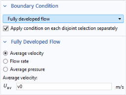
Under Boundary Condition from the Boundary condition list, select Fully developed flow.
4
Locate the Fully Developed Flow section. In the
U
av
text field, type
v0
(which you defined as a Global Parameter).
Symmetry 1
1
In the Physics toolbar click Boundaries
and choose Symmetry
.
2
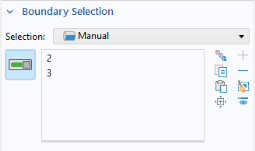
Select Boundaries 2 and 3 only.
Outlet 1
1
In the Physics toolbar click Boundaries
and choose Outlet
.
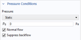
The default outlet condition specifies a zero relative pressure.
2
Go to the Settings window for Outlet. Select Boundary 7 only.
3
In the Settings window for Outlet, locate the Pressure Conditions section. Select the Normal flow checkbox.
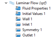
The sequence of nodes in the Model Builder under Laminar Flow should match the figure. The ‘D’ in the upper-left corner of a node means it is a default node.
All other boundaries now have the default wall condition.