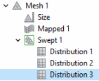
Mesh 1
Set up the mesh for the model. Use a mapped mesh on the top boundaries, and a swept mesh for remaining of the geometry.
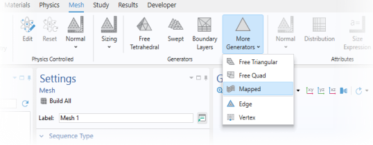
Add a Mapped on the Topmost Boundary
1
In the Mesh toolbar, click
More Generators and choose Mapped.
2
Select Boundary 20 only. (This is the topmost boundary of the geometry.)
3
Click
Build Mesh.
Add a Swept Mesh
1
In the Mesh toolbar, click
Swept.
Distribution of Mesh Elements in the Negative Electrode
1
Right-click Swept 1 and choose Distribution.
By the use of Distribution nodes you can control the resolution in the
z
direction of the individual layers of the cell.
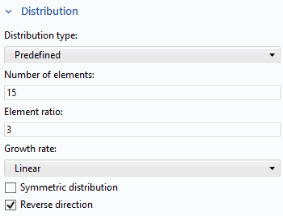
2
In the Settings window for Distribution, locate the Domain Selection section.
3
From the Selection list, choose Negative Electrode.
4
Locate the Distribution section. From the Distribution type list, choose Predefined.
5
In the Number of elements text field, type
15
.
6
In the Element ratio text field, type
3
.
Proceed similarly for the other domains, with different number of element and ratio settings as follows:
Distribution of Mesh Elements in the Separator
1
In the Model Builder window, right-click Swept 1 and choose Distribution.
2
In the Settings window for Distribution, locate the Domain Selection section.
3
From the Selection list, choose Separator.
4
Locate the Distribution section. In the Number of elements text field, type
4
. Keep the other default settings.
Distribution of Mesh Elements in the Positive Electrode
1
Right-click Swept 1 and choose Distribution.
2
In the Settings window for Distribution, locate the Domain Selection section.
3
From the Selection list, choose Positive Electrode.
4
Locate the Distribution section. From the Distribution type list, choose Predefined.
5
In the Number of elements text field, type
15
.
6
In the Element ratio text field, type
3
.
7
Select the Reverse direction checkbox.
8
Click
Build Mesh.
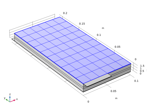
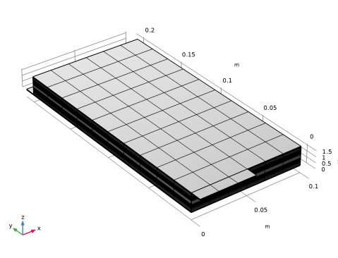
The finalized mesh should now look as follows.