|
2
|
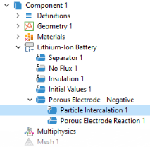
In the Settings window for Porous Electrode, type Porous Electrode - Negative in the Label text field.
|
|
5
|
|
6
|
|
7
|
|
2
|
|
3
|
|
3
|
|
1
|
In the Physics toolbar, click
|
|
4
|
|
5
|
|
6
|
|
1
|
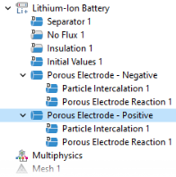
Click Particle Intercalation 1 child node and in the Particle Transport Properties section, in the rp text field, type rp_pos.
|
|
4
|
|
5
|