In order to use the Circuit Extractor add-in, a Stationary Source Sweep or a
Frequency Domain Source Sweep must be solved for the physics of interest. Matrices that are generated from solving such studies are then used for generating the equivalent circuit. After solving, you only need to select the
Equivalent Circuit, select the
Evaluation Group corresponding to the desired solution, and press the
Extract Circuit button. This will open a window for saving the extracted SPICE file. An example of the user interface is shown in
Figure 1, along with the corresponding circuit.
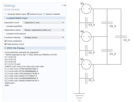
The Settings window toolbar for this add-in contains three buttons. The
Generate Matrix Input button generates all possible lumped matrices from the existing solutions. These matrices are placed in
Evaluation Group features under
Results. The size of these matrices is controlled by the source sweep study solved in the model, which by default scans over the terminals that are defined at the physics level. The order of the rows and columns is the same as the numbering of the feeding elements in the original physics interface. This numbering is also shared by the extracted circuit. The
Extract Circuit button runs the add-in as specified by the given settings, and saves the output. Finally, the
Reset to Default button resets all settings in the add-in to their default values.
This section contains the user input. In the Equivalent Circuit drop down menu, you can select which equivalent circuit analogy should be used for the model. The options are
Resistors R only,
Inductors L only,
Capacitors C only,
R and L (series, diagonal R),
R and C (parallel, diagonal R),
R, L, and C (parallel C, diagonal R), as well as
Impedances Z. Based on the choice, different lumped inputs must be specified in the following sections.
Finally, under Lumped circuit options, there are others settings that can be used to modify the extracted circuit. In particular, the
Conductor feeding drop down menu allows you to specify if each conductor should have a
Voltage source, a
Current source, or
No feeding element. Furthermore, the
Close conductors checkbox determines whether or not it should be assumed that each conductor has both connections closed onto the same ground. If checked, the circuit becomes closed since no extra elements are needed. The
Keep Electrical Circuit checkbox instead determines if the Electrical Circuit physics interface should be kept after the circuit extraction has finished. If unchecked, only the SPICE file is saved.
