Pressure Acoustics, Frequency Domain
Pressure Acoustics 1
1
In the Model Builder window, under Component 1 (comp1) > Pressure Acoustics, Frequency Domain (acpr) click Pressure Acoustics 1.
2
In the Settings window for Pressure Acoustics, locate the Model Input section.
3
In the
T
text field, type
T0
.
4
In the
pA
text field, type
p0
.
Use the Port boundary condition to define the inlet and outlet. The port condition is superior to the classical radiation condition in waveguide configurations. This is particularly the case when nonplane wave modes start to propagate. This happens above the first cutoff frequency. For the present model the cutoff frequency for the first nonplane mode (m = 1 and n = 0) is at 2514 Hz so this mode should be included. The variable
acpr.port2.fc
gives the cutoff frequency of the modes (here for the mode defined on the Port 2 condition).
Note that when including an azimuthal mode in a circular port, it is necessary to add both possible azimuthal angle dependencies (sine and cosine), each as a different Port condition. To get a complete basis for the modal expansion at the boundary, both the since and cosine variants of the mode need to be included, as these modes are orthogonal.
Port 1
1
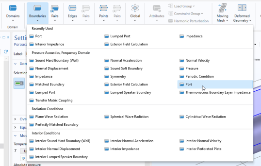
In the Physics toolbar, click Boundaries and choose Port.
2
In the Settings window for Port, locate the Boundary Selection section.
3
From the Selection list, choose Inlet.
4
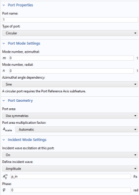
Locate the Port Properties section. From the Type of port list, choose Circular.
5
Locate the Incident Mode Settings section. In the
A
in
text field, type
p_in
.
Circular Port Reference Axis 1
1
Right-click Port 1 and choose Circular Port Reference Axis, under the Points submenu.
2
In the Settings window for Circular Port Reference Axis, locate the Point Selection section.
3
Click Clear Selection.
4
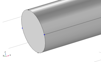
Select Points 1 and 4 only.
Select two points that define a reference axis for the azimuthal angle. The setting is in general necessary when higher order azimuthal modes are used and/or necessary.
Port 2
1
In the Model Builder window, under Component 1 (comp1) > Pressure Acoustics,
2
Frequency Domain (acpr) right-click Port 1 and choose Duplicate.
3
In the Settings window for Port, locate the Port Mode Settings section. In the m text field, type 1.
4
Locate the Incident Mode Settings section. From the Incident wave excitation at this port list, choose Off.
Port 3
1
Right-click Port 2 and choose Duplicate.
2
In the Settings window for Port, locate the Port Mode Settings section.
3
From the Azimuthal angle dependency list, choose Cosine.
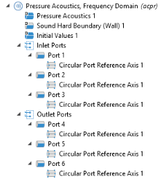
Proceed to add three port conditions also on the Outlet boundary with the same properties as the inlet ports. One mode (0,0) and two mode (1,0) with the two different Azimuthal angle dependency options, Sine and Cosine. All the ports at the outlet have the Incident wave excitation set to Off.
Then group the ports by selecting the three Ports, right click and select Group. This step is only for organizing the user interface.
Now, add a Poroacoustics model for the absorptive liner domain. You will deactivate this domain when configuring the first study step.