Electric Insulation (for Geometry Analysis)
The Electric Insulation subnode is available from the context menu (right-click the Geometry Analysis parent node) or from the Physics toolbar, 
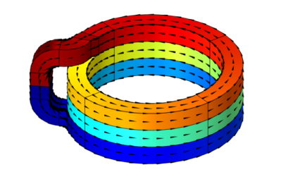
Attributes menu. It is particularly useful for interior boundaries (when the coil is compacted, and the turns touch, see Figure 5-4). It applies to the coil direction field generated by the Coil Geometry Analysis study step.
Figure 5-4: A coil geometry with turns that are geometrically unified, yet electrically separated. The electric insulation boundary condition can be used to override the electrical continuity that applies to interior boundaries by default.
When the Conductor model of the Coil feature is set to Single conductor, the Electric Insulation affects the externally applied currents only, not the currents resulting from electromagnetic induction in the model itself. For this reason, the single conductor with electric insulation should be used in the (quasi) static regime only.
When the Conductor model of the Coil feature is set to Homogenized multiturn, the Electric Insulation works for higher frequencies as well, as both external and induced currents are forced along the same path.
For low frequencies, the Homogenized multiturn option can be considered as an approximation of the Single conductor one. For higher frequencies, you should consider having a gap between the turns, or using the Contact Impedance boundary feature available in The Magnetic and Electric Fields Interface.