Bipolar Transistors
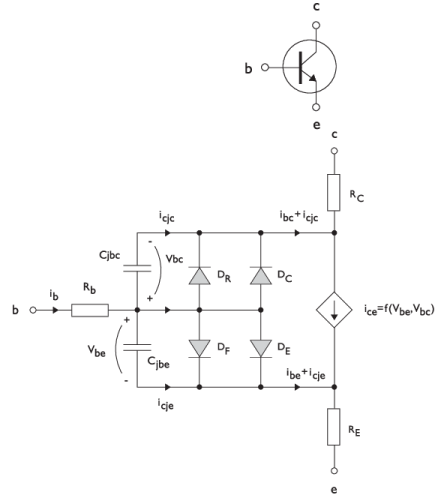
Figure 6-1
illustrates the equivalent circuit for the npn bipolar junction transistor.
Figure 6-1:
A circuit for the bipolar transistor.
The pnp transistor model is similar in all regards to the npn transistor, with the difference that the polarities of the currents and voltages involved are reversed. The following equations are used to compute the relations between currents and voltages in the circuit:
There are also two capacitances that use the same formula as the junction capacitance of the diode model. In the parameter names below, replace
x
with C for the base–collector capacitance and E for the base–emitter capacitance.
The model parameters are listed in the table below.
Table 6-1:
Bipolar Transistor Model Parameters.
Parameter
Default
Description
B
F
100
Ideal forward current gain
B
R
1
Ideal reverse current gain
C
JC
0 F/m
2
Base–collector zero-bias depletion capacitance
C
JE
0 F/m
2
Base–emitter zero-bias depletion capacitance
F
C
0.5
Breakdown current
I
KF
Inf (A/m
2
)
Corner for forward high-current roll-off
I
KR
Inf (A/m
2
)
Corner for reverse high-current roll-off
I
S
10
-15
A/m
2
Saturation current
I
SC
0 A/m
2
Base–collector leakage saturation current
I
SE
0 A/m
2
Base–emitter leakage saturation current
M
JC
1/3
Base–collector grading coefficient
M
JE
1/3
Base–emitter grading coefficient
N
C
2
Base–collector ideality factor
N
E
1.4
Base–emitter ideality factor
N
F
1
Forward ideality factor
N
R
1
Reverse ideality factor
R
B
0
Ω⋅
m
2
Base resistance
R
BM
0
Ω⋅
m
2
Minimum base resistance
R
C
0
Ω⋅
m
2
Collector resistance
R
E
0
Ω⋅
m
2
Emitter resistance
T
NOM
298.15 K
Device temperature
V
AF
Inf (V)
Forward early voltage
V
AR
Inf (V)
Reverse early voltage
V
JC
0.71 V
Base–collector built-in potential
V
JE
0.71 V
Base–emitter built-in potential