Tutorial 3: Electrical Heating in a Busbar
This tutorial demonstrates the use of multiphysics modeling in COMSOL Multiphysics with the AC/DC Module. You will learn how to use one of the many preconfigured multiphysics combinations.
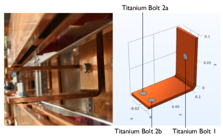
The model that you are about to create analyzes a busbar designed to conduct a high amount of direct current in an industrial setting (see picture below). The current conducted in the busbar, from bolt 1 to bolts 2a and 2b, produces heat due to the resistive losses, a phenomenon referred to as Joule heating. The busbar is made of copper, while the bolts are made of a titanium alloy. Busbar bolts are usually made of steel, but in this example, we will assume a highly corrosive environment. Therefore, a titanium alloy was chosen.
Under normal operational conditions, the currents are predominantly conducted through the copper. This example, however, illustrates the effects of an unwanted electrical loading of the busbar through the bolts. The fact that there are different materials is important because titanium has a lower electric conductivity than copper and will be subjected to a higher current density.
The goal of your simulation is to precisely calculate how much the busbar heats up. The Joule heating effect is described by conservation laws for electric current and energy. Once solved for, the two conservation laws give the temperature and electric field, respectively. All surfaces, except the bolt contact surfaces, are cooled by natural convection in the air surrounding the busbar. You can assume that the exposed parts of the bolt do not contribute to the cooling or heating of the device. The electric current flowing through the upper-right vertical bolt surface is 160 A and the potential at the two horizontal surfaces of the lower bolts is 0 V.