Electrical Circuit (cir)
Add a resistor and a voltage source in series with the inductor.
Voltage Source 1
1
In the Model Builder select the Electrical Circuit (cir)
node.
2
On the Electrical Circuit toolbar click Voltage Source
.
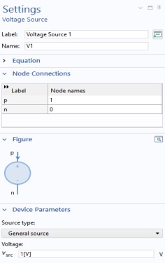
Go to the Settings window for Voltage Source. The default settings correspond to a DC source of 1 V. Under Node Connections enter
1
and
0
in the Node names table as in the figure to the right.
Resistor 1
1
On the Electrical Circuit toolbar click Resistor
.
2
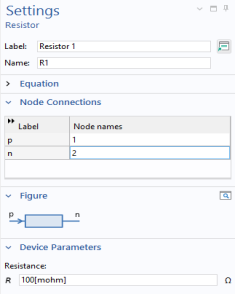
Go to the Settings window for Resistor. Under Node Connections enter
1
and
2
in the Node names table as in the figure to the right.
3
Under Device Parameters in the
R
text field, enter
100[mohm]
.
External I Vs. U 1
There is a special feature for connecting the circuit to the finite elements model.
1
On the Electrical Circuit toolbar click External I Vs. U
.
2
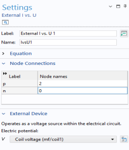
In the Settings window for External I Vs. U under Node Connections, enter Node names as in to the figure to the right.
3
Under External Device, from the Electric potential V list choose Coil voltage (mf/coil1).
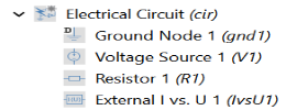
The sequence of nodes under Electrical Circuit should match this figure.