Definitions - Selections
Use the Selection feature available under the Definitions node to make the setup of materials and physics interfaces easier. Start by defining the domain group for the inductor winding and continue by adding other useful selections. These steps illustrate how to set up the Explicit nodes and rename the geometric selections accordingly.
1
In the Definitions toolbar, click Explicit
.
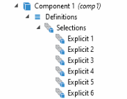
2
Repeat Step 1 and add a total of six (6) Explicit nodes
. Or right-click the first Explicit node and select Duplicate
.
The following steps are done one at a time for each node using the table below.
3
In the Model Builder click an Explicit node
to open the Settings window.
Note:
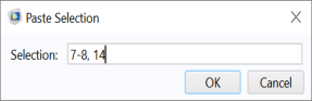
There are many ways to select geometric entities. When you know the domain to add, such as in this exercise, you can click the Paste Selection button
and enter the information in the Selection text field. In this example for the Explicit 1 node, enter
7,8,14
in the Paste Selection window. For more information about selecting geometric entities in the Graphics window, see the
COMSOL Multiphysics Reference Manual
.
4
In the Settings window under Input Entities, select Domain from the Geometric entity level list. Use the table as a guide, and in the Graphics window, select the domains as indicated. Then rename the node by changing its Label in the Settings window.
Default Node Name
Select These Domains
New Name for the Node
Explicit 1
7, 8, and 14
Winding
Explicit 2
9
Gap
Explicit 3
6
Core
Explicit 4
1–4 and 10–13
Infinite Elements
Explicit 5
1–6 and 9–13
Nonconducting
Explicit 6
5,6, and 9
Nonconducting without IE
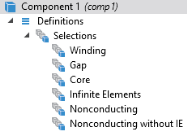
5
After renaming all the nodes under Definitions, the sequence of nodes should match this figure.