Tutorial 1: Evaluating the Performance of an Insulator
Insulators are widely used in high voltage power transmission lines to support the weight of suspended conductors without allowing the current to flow through the tower to ground. A typical high voltage composite insulator rated at 110 kV is shown in Figure 7.
High voltage insulators are usually made from glass, porcelain, or composite polymer materials. Composite insulators are typically composed of a central rod made of fiber reinforced plastic and an outer weather shed made of silicone rubber. The weather shed makes some parts of the insulator stay dry to withstand the flashover in wet weather.
Figure 7: The high voltage insulator geometry.
The electric field is not distributed evenly across the insulator but is strongest at the sheds nearest to both ends, which flashover first under an overvoltage. Metal grading rings are usually installed around the sheds at both ends, to reduce the nonuniformity of the electric field and increase the flashover voltage.
Under static conditions, the electric potential V is defined by E = −∇V. Using this together with the constitutive relation D = εrε0E and setting the free space charge to zero, one can rewrite Gauss’ law as a variant of Poisson’s equation
where ε0 is the permittivity of vacuum and 
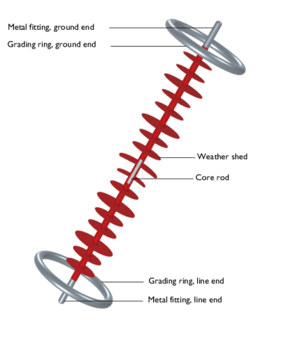
εr the relative permittivity of the material. This equation can be solved by using the Electrostatics interface. To obtain a unique solution, electric boundary conditions are applied to the line end with the overvoltage amplitude V = 500 kV and to the ground end with V = 0.
The first step is to perform an electrostatic analysis without grading rings.