Introduction
The AC/DC Module is used by engineers and scientists to understand, predict, and design electric and magnetic fields in static, low-frequency, and transient applications. Simulations of this kind result in more powerful and efficient products and engineering methods. The module allows its users to quickly and accurately predict electromagnetic field distributions, electromagnetic forces, and power dissipation in a proposed design. Compared to traditional prototyping, COMSOL Multiphysics helps to lower costs and can evaluate and predict entities that are not directly measurable in experiments. It also allows the exploration of operating conditions that would destroy a real prototype or be hazardous.
The AC/DC Module includes stationary and dynamic electric and magnetic fields in two-dimensional and three-dimensional spaces along with traditional circuit-based modeling of passive and active devices. All modeling formulations are based on Maxwell’s equations or subsets and special cases of these, together with various constitutive relations and material models. The modeling capabilities are accessed via a number of predefined physics interfaces, referred to as AC/DC interfaces, which allow you to set up and solve electromagnetic models. The AC/DC interfaces cover electrostatics, DC current flow, magnetostatics, AC and transient current flow, AC and transient magnetodynamics, and AC electromagnetic (full Maxwell) formulations.
Under the hood, the majority of the AC/DC interfaces formulate and solve the differential form of Maxwell’s equations together with initial and boundary conditions. The equations are solved using the finite element method with numerically stable element discretization in combination with state-of-the-art algorithms for preconditioning and solution of the resulting sparse equation systems. Two of the AC/DC interfaces are based on boundary integral formulations of Maxwell’s equations and are solved using the boundary element method. The results are presented in the graphics window through predefined plots of electric and magnetic fields, currents, and voltages, or as expressions of the physical quantities that you can define freely, as well as derived tabulated quantities (for example resistance, capacitance, inductance, electromagnetic force, and torque) obtained from a simulation.
The workflow in the module is straightforward and is described by the following steps: define the geometry, select materials, select a suitable AC/DC interface, define boundary and initial conditions, define the finite or boundary element mesh, select a solver, solve the model, and visualize the results. All these steps are accessed from the COMSOL Desktop. The solver selection step is usually carried out automatically using the default settings, which are already tuned for each specific AC/DC interface.
The AC/DC Module application library describes the available features using tutorial and benchmark examples for the different formulations. The library contains models for industrial equipment and devices, tutorial models, and benchmark models for verification and validation of the AC/DC interfaces.
This guide will give you a jump start to your modeling work. It has examples of the typical use of the module, a list of all the AC/DC interfaces including a short description of each, and three tutorial models that introduce the modeling workflow. The appended models, Tutorial 1: Evaluating the Performance of an Insulator, Tutorial 2: Computing the Impedance of a 3D Inductor, and Tutorial 3: Electrical Heating in a Busbar are examples of modeling capacitive, inductive, and resistive devices, respectively.
The Use of the AC/DC Module
The AC/DC Module can model electric, magnetic, and electromagnetic fields in static and low-frequency applications. The latter means that it covers the modeling of devices that are up to about 0.1 electromagnetic wavelengths in size. Thus, it can be used to model nanodevices up to optical frequencies, or human size devices operated at frequencies up to 10 MHz.
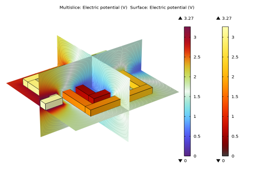
AC/DC simulations are frequently used to extract circuit parameters. Figure 1 on the next page shows the electric potential and the magnetic flux lines for a microscale square inductor, used for LC bandpass filters in microelectromechanical systems (MEMS). A DC voltage is applied across the electrically conducting square shaped spiral, resulting in an electric current flow that in turn generates a magnetic field through and around the device.
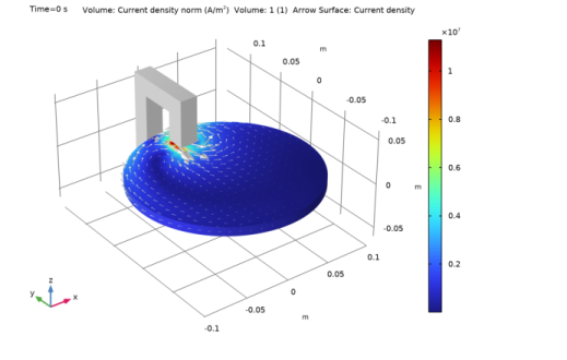
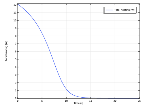
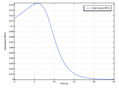
The distribution and strength of electric and magnetic fields arising from applied current and voltage can be translated into resistance, capacitance, and inductance values for an equivalent circuit model that is easy to understand and analyze from both qualitative and quantitative perspectives. This kind of understanding in terms of a simplified model is usually the first step when creating or improving a design.
Another common use of this module is to predict forces and motion in electric motors and actuators of a wide range of scales.
Figure 1: Electric potential distribution and magnetic flux lines for a MEMS inductor.
In Figure 2, Figure 3, and Figure 4, the dynamics of a magnetic brake is shown. The brake consists of a disc of conductive material and a permanent magnet. The magnet generates a constant magnetic field, in which the disc is rotating. When a conductor moves in a magnetic field it induces currents, and the Lorentz forces from the currents counteracts the spinning of the disc.
The braking torque is computed from the magnetic flux and eddy current distributions. It is then fed into a rigid body model for the dynamics of the spinning disc that is solved simultaneously with the electromagnetic model.
Figure 2: The eddy current magnitude and direction in the spinning disc of a magnetic brake.
Figure 3: The time evolution of the braking torque.
Figure 4: The time evolution of the dissipated power.
The AC/DC Module includes a range of tools to evaluate and export results, for example, the evaluation of force, torque, as well as lumped circuit parameters like resistance, capacitance, inductance, impedance, and scattering matrices (S-parameters). Lumped parameters can also be exported in the Touchstone file format.
The combination of fully distributed electromagnetic field modeling and simplified circuit-based modeling is an ideal basis for design, exploration, and optimization. More complex system models can be exploited using circuit-based modeling while maintaining links to full field models for key devices in the circuit. In this way, the combination allows for design innovation and optimization on both levels.