Governing Equations
The dependent variable in the Layered Shell interface is the displacement field. The dependent variable is available in the product geometry.
The governing differential equations, constitutive relations, the definition of deformation, stresses, strains are same as in the 3D elasticity theory as described for the Solid Mechanics interface.
See Solid Mechanics Theory for more details.
Gradient Definition
In the analysis of deformations in 3D, the deformation gradient F is defined as
An equivalent definition of a deformation gradient in a product geometry of a layered shell can be written as
(3-249)
where
z is the extra dimension thickness coordinate (varies between 0 and d)
n is the positive normal direction
Equation 3-249 is exact for flat laminates. For curved laminates, the deformation gradient expression must account for the surface area of each layer. The deformation gradient in a product geometry of a curved layered shell can be written as
where
Xr are the reference surface coordinates
zoff is the relative midplane offset
d is the laminate thickness
In some applications, it is required to model variable thickness layers. This is achieved by scaling the constant thickness of the layer (d_layer) using a thickness scale factor (lsc), which could be a function of surface coordinates. The deformation gradient in a scaled product geometry of a curved layered shell can be written as
where
zs is the scaled extra dimension thickness coordinate (varies between 0 and ds)
ds is the scaled laminate thickness
Area Scale Factor
For a curved laminate, the change in surface area of each layer should be accounted for while integrating the energy expressions. The area scale factor (ASF) for each layer of the laminate can be defined as:
Length Scale Factor
For conditions applied to edges, a similar length scale factor (LSF) is required. It is formally defined as
where t is the tangent to the edge. For an internal edge, it is possible that there is a discontinuity in thickness or offset. In such a case, the line scale factor will be an average. Edge conditions are not well defined in such situations because the position of the midsurface can be discontinuous. In practice, errors caused by such effects are small.
The LSF variable is computed from the principal curvatures, see Curvature Variables in the COMSOL Multiphysics Reference Manual.
Integration
All volume integrals over a layered shell element are split into a surface integration and a through-thickness integration. Both integrations are performed numerically. The surface geometry is used for surface integration and the extra dimension geometry is used for the through-thickness integration. It is thus possible to enter data which explicitly depends on the thickness direction.
Unlike a single layer shell, where all material properties are evaluated at the reference surface, different material and fiber orientation can be specified in each layer of the composite laminate. Formally this can be written as:
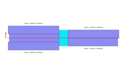
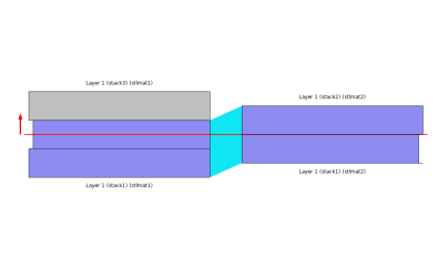
As discussed in the previous section, the area scale factor (ASF) is included for curved laminates since the layers have different surface area. This is independent of whether an offset is used or not, but the offset affects the scale factor.
The layer thickness scale factor (lsc) is also accounted in the integrations when variable thickness layers are present in the model.
Discretization
The Layered Shell interface can use different shape orders for the displacement field in the reference surface and in the through-thickness direction. The shape orders used can be divided into categories:
Based on the above two categories, 9 different elements are available:
Figure 3-56: Element having linear shape order.
Figure 3-57: Elements having quadratic and cubic shape orders.
Figure 3-58: Elements having different shape orders on the reference surface and in the through-thickness direction.
Fold-Line Connection
When two or more layered shell surfaces meet at an angle, the displacement field cannot be same on the side faces of all the layered shell surfaces. Thus, a slit condition is needed on the common edges and a connection needs to be established between the displacement field of different layered shell surfaces sharing an edge.
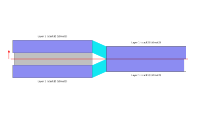
This is automatically handled in COMSOL Multiphysics. The automatic search for these fold lines compares the normals of all the layered shell surfaces sharing an edge. If the angle between the normals is larger than a certain angle (default 3°) it is considered as a fold line.
In order to connect the displacement field of different shell surfaces meeting at a fold line, the following two conditions are needed:
where ub is the displacement vector at the reference surface location in the through-thickness direction.
where ur is the displacement vector in the through-thickness direction relative to the displacement vector at the reference surface location.
Layered Shell Continuity
Different layered materials have their own virtual extra dimension geometry and that is why, by default, two layered materials sharing a common edge in the geometry do not have a continuous displacement field. Thus, when two layered shell surfaces having different layered materials meet side-by-side, a displacement continuity needs to be established in the through-thickness direction on the common edge.
For an example, a layered material having 3 layers shares a common edge with another layered material having 2 layers. For that case, some of the ways you can connect the two layered materials in the through-thickness direction are as follows:
 
In case the two layered materials have normal orientation in opposite directions, you may want to switch the Connection type from Straight to Twisted in the Connection Settings section of the Continuity node in order to connect points in extra dimension which are geometrically close to each other.