Solid Mechanics
The Solid Mechanics interface offers the most general modeling of structural mechanics problems and is based on general principles of continuum mechanics. It is the interface which contains the largest number of material models, and the most advanced boundary conditions.
The drawback with using solid elements is that the models can become computationally expensive, especially in 3D. For structures which are thin or slender, you should consider using one of the specialized physics interfaces, described in the actions Shell and Plate, Membrane, Beam, Pipe Mechanics, Truss, or Wire.
3D Solid Geometry
The degrees of freedom (dependent variables) in 3D are the global displacements u, v, and w in the global x, y, and z directions, respectively.
Figure 2-1: Loads and constraints applied to a 3D solid using the Solid Mechanics interface.
2D Geometry
Plane Stress
The plane stress variant of the 2D physics interface is useful for analyzing thin in-plane loaded plates. For a state of plane stress, the out-of-plane components of the stress tensor are zero.
Figure 2-2: Plane stress is used to model plates where the loads are only in the plane; it does not include any out-of-plane stress components.
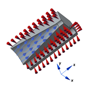
The 2D physics interface for plane stress allows loads in the x and y directions, and assumes that these are constant throughout the material’s thickness, which can vary with x and y. The plane stress condition prevails in a thin (compared to the in-plane dimensions) flat plate in the xy-plane loaded only in its own plane and without any z direction restraint.
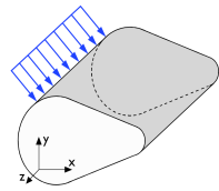
The plane stress conditions are enforced by adding extra degrees of freedom for the transverse strain, which are determined so that the transverse stress is zero in a weak sense.
Plane Strain
In the plane strain variant of the 2D physics interface, the assumption is that all out-of-plane strain components of the total strain tensor εz, εyz, and εxz are zero.
Figure 2-3: A geometry suitable for plane strain analysis.
Loads in the x and y directions are allowed. The loads are assumed to be constant throughout the thickness of the material, but the thickness can vary with x and y. Formally, the plane strain conditions require that the ends of the object are constrained in the z direction, but it is often also used for central parts of an object that is long in the z direction (compared to the in-plane dimensions). One example is a long tunnel along the z-axis where it is sufficient to study a unit-depth slice in the xy-plane.
Generalized Plane Strain
Generalized plane strain is similar to plane strain in the sense that transverse stresses can develop in the 2D cross section of a long object. The requirement that the out-of-plane strain is zero, is however relaxed. Instead, an assumption about zero resulting force in the transverse direction is used. Optionally, assumptions about zero bending moments over the cross section can be added. Generalized plane strain conditions prevail in the inner parts of a long object with free ends. For many cases, generalized plane strain conditions is the 2D approximation that is closest to a full 3D solution.
2D Axisymmetric Geometry
The axisymmetric variant of the Solid Mechanics interface uses cylindrical coordinates r, φ (phi), and z. All properties are independent of the azimuthal angle φ.
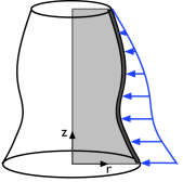
In the default version of the interface, displacements occur only in the rz-plane, and there are two degrees of freedom, u and w. By selecting the Include circumferential displacement option, you can model also torsion around the axis of rotational symmetry. The azimuthal rotation degree of freedom v is then included. In addition, many features such as loads, allow values to be entered in the φ direction.
The 2D axisymmetric geometry is viewed as the intersection between the original axially symmetric 3D solid and the half plane φ = 0, r ≥ 0. Therefore, the geometry is drawn only in the half plane r ≥ 0, and the original 3D solid is recovered by rotating the 2D geometry about the z-axis.
Figure 2-4: Rotating a 2D geometry to recover a 3D solid.
When working with resultants, for example loads and reaction forces, for an axisymmetric model, they refer to the whole circumference.
Axisymmetric Twist and Bending: Application Library path Structural_Mechanics_Module/Verification_Examples/axisymmetric_twist_and_bending
1D Geometry
Modeling Solid Mechanics in 1D implies that there are no variations in two transverse directions. For pure structural mechanics, this is a situation that is seldom of interest in practical engineering. The main application is to study various multiphysics phenomena.
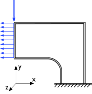
The geometry is a line, and the degree of freedom (dependent variable) is the displacement u in the global x direction. Plane stress, plane strain, or generalized plane strain assumptions can be used. The out-of-plane formulation can be selected independently in the y and z directions.
For plane stress, additional degrees of freedom are added to account for the strains in the out-of-plane directions.
The generalized plane strain assumption adds one global variable for the additional strain in the y or z direction, and the corresponding transverse strain component can vary linearly throughout the cross sectional area.
1D Axisymmetric Geometry
The axisymmetric version of the 1D Solid Mechanics interface uses cylindrical coordinates. All properties are independent of the azimuthal angle φ and the axial z direction.
The geometry is a line, which represents a disk because of the axial symmetry. The line is drawn only in the half plane r ≥ 0. Displacement occurs only in the radial direction, and there is one degree of freedom, u, the displacement in the global r direction.
Plane stress, plane strain, or generalized plane strain assumptions can be used in the axial direction. For plane stress, one additional degree of freedom is added to account for the strain in the z direction. The generalized plane strain assumption adds one global variable for the additional strain in the z direction.