The Structural Mechanics Module Physics Interfaces
The figures below show the physics interfaces that are available in the COMSOL Model Wizard and included with the Structural Mechanics Module and its related products. In addition to the structural mechanics capabilities, the module also has substantial multiphysics capabilities, including electromagnetics, acoustics, fluid flow, heat transfer, poroelasticity, piezoelectricity, and magnetostriction.
Figure 5: The 3D component physics interfaces available with the Structural Mechanics Module. Several of the physics interfaces require additional licenses.
Figure 6: The 2D component physics interfaces.
A short description of the main Structural Mechanics interfaces follows.
Solid mechanics
The Solid Mechanics interface () defines the quantities and features for stress analysis and general linear and nonlinear solid mechanics. In 1D and 2D, plane stress, plane strain, and generalized plane strain formulations are available. In 2D axisymmetry, there are formulations with and without twist.
The Linear Elastic Material node is the default material model. The elastic material model can be expanded with features for thermal expansion, hygroscopic swelling, viscoelasticity, damping, and initial stress and strain. The description of elastic materials in the module includes isotropic, orthotropic, and fully anisotropic materials. The material can be activated or deactivated based on for example time or temperature. A number of preset study types are available for solid mechanics (shown below). Also, see Physics Interface Guide by Space Dimension and Study Type.
Figure 7: Study types for 3D Solid Mechanics.
Geomechanics, Nonlinear Structural Materials, Composite Materials, Rotordynamics, and Fatigue
There are five additional modules available to enhance the Structural Mechanics Module: the Geomechanics Module, the Nonlinear Structural Materials Module, the Composite Materials Module, the Rotordynamics Module, and the Fatigue Module.
The Multibody Dynamics Module is a related product, which does not require the Structural Mechanics Module. Here, you can study rigid and flexible bodies connected by different types of mechanical joints, gears, cam-follower mechanisms, springs, and dampers. You can also model lumped mechanical systems, defined by components like mass, spring, damper, or impedance.
You will also find a subset of the structural mechanics capabilities in the MEMS Module and the Acoustics Module.
The exact contents of the menus and windows shown in this document may vary depending on the licenses you have. All illustrations assume the presence of these additional modules, even though the examples given only require the Structural Mechanics Module.
Shell and Plate
The Shell interface () is intended for mechanical analysis of thin-walled structures. The formulation used in the Shell interface is a Mindlin–Reissner type, which means that transverse shear deformations are accounted for. It can be used for rather thick shells as well as thin ones. It is possible to prescribe an offset in a direction normal to a selected surface, which for example can be used when meshing imported geometries. The Shell interface also includes other features such as damping, thermal expansion, and initial stresses and strains. Stresses in welds can be evaluated for connected shells. Special features for connecting shells through a large number of spot welds or fasteners are available. With the Composite Materials Module, it is also possible to analyze layered shells. Through the addition of the Nonlinear Structural Materials Module, it is possible to model material behavior like plasticity, hyperelasticity, creep, and viscoplasticity.
The Plate interface () is a 2D analogy to the 3D Shell interface. Plates are similar to shells, but act in a single plane and usually act only with out-of-plane loads. The formulation and features for this physics interface are similar to those for the Shell interface.
Membrane
The Membrane interface () is used for thin membranes, which can be considered as curved plane stress elements in 3D, having in-plane as well as out-of-plane deformation. The difference between a shell and a membrane is that a membrane does not possess any bending stiffness. Thin films and fabrics are structures suited for modeling with the Membrane interface. In order to be stable, a membrane must be in tension; if not, it will wrinkle. A special formulation in the Membrane interface makes it possible to model also wrinkling. With the Nonlinear Structural Materials Module, hyperelasticity, nonlinear elasticity, plasticity, creep, and viscoplasticity can be modeled in addition to the default linear elastic material. With the Composite Materials Module, it is also possible to analyze layered membranes.
Beam
The Beam interface () is intended for the modeling of slender structures (beams) that can be fully described by their cross-section properties, such as area and moment of inertia. The Beam interface defines stresses and strains using Hermitian elements and Euler–Bernoulli or Timoshenko theory. Beam elements are used to model both planar and three-dimensional frame structures. This physics interface is also suitable for modeling reinforcements of solid and shell structures. It includes a library for rectangular, box, circular, pipe, hat, H-profile, U-profile, C-profile, and T-profile beam sections. Additional features include damping, thermal expansion, and initial stresses and strains.
Beam Cross Section
A separate 2D physics interface called the Beam Cross Section interface () can be used to compute the properties of general cross sections, to be used as inputs in beam analyses. The interface can also be used for detailed stress evaluation in beams, given the forces and moments acting on the section. With the 3D version of the same interface, it is also possible to plot the full 3D representation of the stresses in a beam, given the section forces.
Truss
The Truss interface () can be used to model slender structures that can only sustain axial forces. Trusses are modeled using Lagrangian shape functions, which allow the specification of small strains as well as Green–Lagrange strains for large deformations. Additional features include damping, thermal expansion, and initial stresses and strains. The default material model is linear elastic, and together with the Nonlinear Structural Materials Module, it is possible to also model plasticity and shape memory alloys.
Pipe Mechanics
The Pipe Mechanics interface () is intended for stress and deformation analysis in pipe systems, either standalone or together with the Pipe Flow interface. Pipes are similar to beams, but stresses from internal pressure and temperature gradients through the pipe wall are part of the formulation. There are also pipe-specific formulations for stress evaluation and stiffness correction in curved pipes.
Wire
The Wire () interface can be used for modeling cables, both prestressed and exposed to gravity forces (sagging cables). Wires are similar to truss elements, but cannot sustain any compressive forces.
Other Structural Mechanics Interfaces
The Thermal Stress, Solid multiphysics interface () combines the Solid Mechanics interface with the Heat Transfer in Solids interface. The temperature field is automatically coupled to a structure’s thermal expansion, and also to any temperature-dependent material properties. Similar interfaces are available also for shells and membranes.
The Joule Heating and Thermal Expansion multiphysics interface () combines three physics interfaces: Joule Heating, Heat Transfer in Solids, and Solid Mechanics. It describes the conduction of electric current in a structure, the subsequent electric heating caused by the ohmic losses, and the thermal stresses induced by the temperature field.
The Piezoelectricity multiphysics interface () combines the Solid Mechanics and Electrostatics interfaces to model piezoelectric materials. The piezoelectric coupling can be in stress–charge or strain–charge form. All solid mechanics and electrostatics functionalities are also accessible through this physics interface, for example, for modeling the surrounding linear elastic solids or air domains. For the Layered Shell interface, the Piezoelectricity, Layered Shell interface () offers similar capabilities.
The Ferroelectroelasticity () and Electrostriction () multiphysics interfaces combine Solid Mechanics and Electrostatics together with the constitutive relationships required to model linear and nonlinear ferroelectric materials with polarization saturation and possible hysteresis. Many piezoelectric materials exhibit such nonlinear ferroelectroelastic behavior at large applied electric fields. This interfaces requires the AC/DC module or the MEMS module.
The Piezomagnetism () and Nonlinear Magnetostriction () multiphysics interfaces combine the Solid Mechanics and Magnetic Fields interfaces to model linear and nonlinear magnetostrictive materials, respectively. The interfaces require the AC/DC module.
A similar multiphysics interface, Magnetomechanics (), combines Solid Mechanics and Magnetic Fields interfaces together with a moving mesh functionality to model the deformation of magnetically actuated structures. For magnetomechanical interaction where some parts are rotating, there is a dedicated multiphysics interface, Magnetic–Elastic Interaction in Rotating Machinery ().
Fluid Flow
There are several Fluid–Structure Interaction (FSI) multiphysics interfaces. These interfaces combine fluid flow with structural mechanics to capture the interactions between fluids and structures. In the Fluid–Solid Interaction () interface, a Solid Mechanics interface and a Single Phase Flow interface model the solid and the fluid, respectively. Together with the CFD Module, also turbulent flow and two-phase flow can be studied. The FSI couplings appear on the boundaries between the fluid and the solid. The Fluid–Structure Interaction interface uses an arbitrary Lagrangian–Eulerian (ALE) method; it combines the fluid flow formulated in an Eulerian description and a spatial frame with solid mechanics formulated in a Lagrangian description and a material (reference) frame.
The Fluid–Solid Interaction, Fixed Geometry () interface can be used to model phenomena where a fluid and a deformable solid structure affect each other, but the displacements of the solid are assumed to be small enough for the geometry of the fluid domain to be considered as fixed during the simulation. Both the fluid loading on the structure and the structural velocity transmission to the fluid can be taken into account.
There are also similar interfaces for coupling shells and membranes to fluid flow, as well as a special interface coupling the Pipe Flow interface to the Pipe Mechanics interface.
The Fluid–Solid Interaction, Conjugate Heat Transfer interface (), combines the FSI functionality with heat transfer in the fluid and solid domains.
There are also multiphysics interfaces targeted at porous flow, such as the Poroelasticity, Solid () interface. It combines Solid Mechanics with Darcy’s Law, to provide a bidirectional coupling between the flow through an elastic matrix and the deformation of the matrix.
The interaction between structures and thin liquid or gas layers can be modeled using the Solid Thin-Film Damping () and Shell Thin-Film Damping () multiphysics interfaces.
Physics Interface Guide by Space Dimension and Study Type
The table below lists the physics interfaces available specifically with this module in addition to those included in the basic COMSOL Multiphysics license.
 
Acoustics
Elastic Waves
Chemical Species Transport
Fluid Flow
Fluid-Structure Interaction
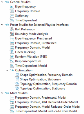
stationary; eigenfrequency; time dependent; time dependent, modal; time dependent, modal reduced-order model; frequency domain; frequency domain, modal; frequency domain, modal reduced-order model; time dependent; response spectrum; random vibration (PSD)
Structural Mechanics
stationary; eigenfrequency; eigenfrequency, prestressed; mode analysis; time dependent; time dependent, modal; time dependent, modal reduced-order model; frequency domain; frequency domain, modal; frequency domain, prestressed; frequency domain, prestressed, modal; frequency domain, modal reduced-order model; frequency domain, AWE reduced-order model; response spectrum; random vibration (PSD); linear buckling; bolt pretension
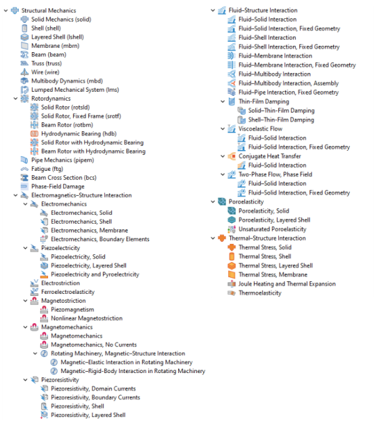
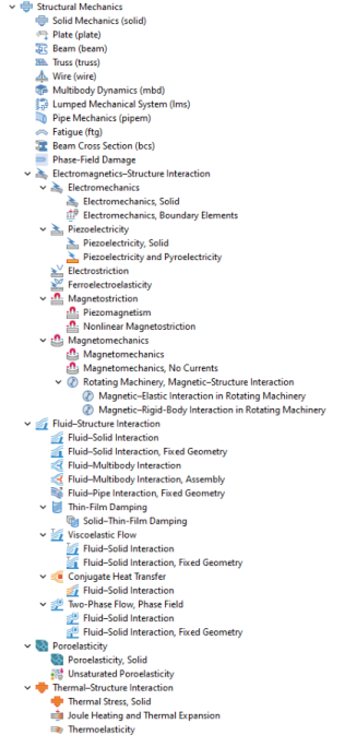
Thermal–Structure Interaction
Piezoelectricity
Magnetomechanics
Electrostriction
Piezoresistivity
Poroelasticity
Mathematics
Moving Interface
1 This physics interface is included with the core COMSOL Multiphysics software but has added functionality for this module.
2 This physics interface is a predefined multiphysics coupling that automatically adds all the physics interfaces and coupling features required.
3 Requires the addition of the AC/DC Module.
4 Requires the addition of the Heat Transfer Module.
5 Requires the addition of the Composite Materials Module.
6 Requires the addition of the CFD Module, or the Polymer Flow, or the Microfluidics Module.
7 Requires the addition of the Pipe Flow Module.
8 Requires the addition of the Porous Media Flow Module.
9 Requires the addition of the AC/DC Module or the MEMS Module.
10 Requires the addition of the Polymer Flow Module.
11 Requires the addition of the Nonlinear Structural Materials Module or the Geomechanics Module.
12 Requires the addition of the MEMS Module.