
|
|
|


|
1·10-3 Pa·s
|
||
|
1.81·10-5 Pa·s
|
||
|
m-1
|
|||||
|
m-2
|
2.48·10-12
|
1.09·10-12
|
0.94·10-12
|
|
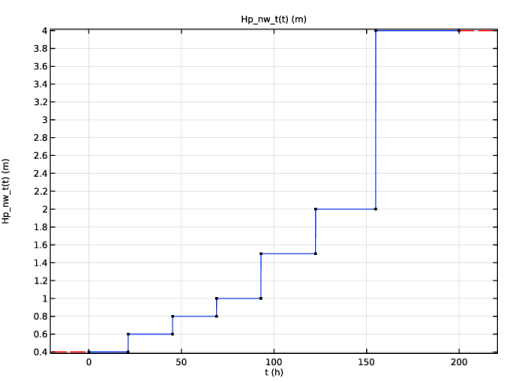
Pressure head (m water)
|
Start time (hours)
|
|
1
|
|
2
|
In the Select Physics tree, select Fluid Flow > Porous Media and Subsurface Flow > Darcy’s Law (dl).
|
|
3
|
Click Add.
|
|
4
|
|
5
|
In the Select Physics tree, select Fluid Flow > Porous Media and Subsurface Flow > Darcy’s Law (dl).
|
|
6
|
Click Add.
|
|
7
|
|
8
|
Click
|
|
9
|
|
10
|
Click
|
|
1
|
|
2
|
|
3
|
Click
|
|
4
|
Browse to the model’s Application Libraries folder and double-click the file twophase_flow_column_parameters.txt.
|
|
1
|
|
2
|
|
3
|
|
4
|
Click
|
|
5
|
Browse to the model’s Application Libraries folder and double-click the file twophase_flow_column_interpolation.txt.
|
|
6
|
Click
|
|
7
|
|
8
|
In the Argument table, enter the following settings:
|
|
9
|
|
10
|
|
1
|
|
2
|
|
3
|
|
4
|
|
5
|
|
6
|
Click to expand the Layers section. In the table, enter the following settings:
|
|
7
|
Click
|
|
1
|
|
2
|
|
3
|
|
1
|
|
2
|
|
3
|
|
4
|
Browse to the model’s Application Libraries folder and double-click the file twophase_flow_column_air_water.txt.
|
|
1
|
|
2
|
|
3
|
|
4
|
Browse to the model’s Application Libraries folder and double-click the file twophase_flow_column_retention_model.txt.
|
|
1
|
|
2
|
|
3
|
|
4
|
Browse to the model’s Application Libraries folder and double-click the file twophase_flow_column_initial_conditions.txt.
|
|
1
|
|
2
|
|
3
|
|
5
|
|
6
|
Browse to the model’s Application Libraries folder and double-click the file twophase_flow_column_lower_layer.txt.
|
|
1
|
|
2
|
|
3
|
|
5
|
|
6
|
Browse to the model’s Application Libraries folder and double-click the file twophase_flow_column_upper_layer.txt.
|
|
1
|
|
2
|
|
3
|
Select the Include gravity checkbox.
|
|
1
|
In the Model Builder window, under Component 1 (comp1) > Darcy’s Law (dl) > Porous Medium 1 click Fluid 1.
|
|
2
|
|
3
|
|
4
|
|
1
|
|
2
|
|
3
|
|
4
|
|
1
|
In the Model Builder window, under Component 1 (comp1) > Darcy’s Law (dl) right-click Porous Medium 1 and choose Duplicate.
|
|
3
|
|
4
|
|
1
|
|
2
|
|
3
|
|
1
|
|
2
|
|
3
|
|
1
|
|
3
|
|
4
|
|
1
|
|
3
|
|
4
|
|
1
|
|
3
|
|
4
|
Select the Include gravity checkbox.
|
|
1
|
|
2
|
|
3
|
|
1
|
|
2
|
|
3
|
|
4
|
|
1
|
|
2
|
|
3
|
|
4
|
|
1
|
In the Model Builder window, under Component 1 (comp1) > Darcy’s Law 2 (dl2) click Initial Values 1.
|
|
2
|
|
3
|
|
1
|
|
3
|
|
4
|
|
1
|
|
3
|
|
4
|
|
1
|
|
2
|
|
3
|
|
1
|
|
2
|
|
3
|
|
4
|
Click
|
|
1
|
|
2
|
|
3
|
|
1
|
|
2
|
|
3
|
|
4
|
|
5
|
|
1
|
|
2
|
|
3
|
|
4
|
|
5
|
|
6
|
Click
|
|
1
|
|
2
|
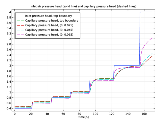
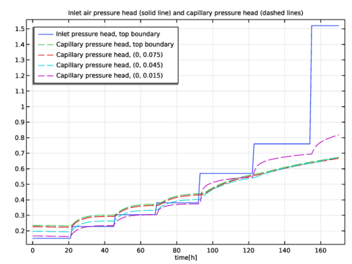
In the Settings window for 1D Plot Group, type Inlet Air Pressure and Capillary Pressure, Air-Water in the Label text field.
|
|
3
|
Locate the Plot Settings section.
|
|
4
|
|
5
|
|
6
|
In the Title text area, type Inlet air pressure head (solid line) and capillary pressure head (dashed lines).
|
|
7
|
|
1
|
|
3
|
|
4
|
|
5
|
|
6
|
|
8
|
|
1
|
|
2
|
In the Settings window for Point Graph, click Replace Expression in the upper-right corner of the y-Axis Data section. From the menu, choose Component 1 (comp1) > Definitions > Variables > Hc - Capillary pressure head - m.
|
|
3
|
Click to expand the Coloring and Style section. Find the Line style subsection. From the Line list, choose Dashed.
|
|
4
|
|
5
|
|
6
|
Select the Description checkbox.
|
|
7
|
|
8
|
|
1
|
|
2
|
|
3
|
|
4
|
|
5
|
Clear the Description checkbox.
|
|
6
|
|
7
|
|
8
|
|
1
|
|
2
|
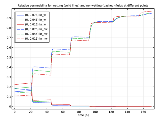
In the Settings window for 1D Plot Group, type Relative Permeabilities at 3 Points in the Label text field.
|
|
3
|
|
4
|
|
5
|
In the Title text area, type Relative permeability for wetting (solid lines) and nonwetting (dashed) fluids at different points.
|
|
6
|
Locate the Plot Settings section.
|
|
7
|
|
8
|
|
1
|
|
2
|
In the Settings window for Point Graph, click Replace Expression in the upper-right corner of the y-Axis Data section. From the menu, choose Component 1 (comp1) > Definitions > Variables > kr_w - Relative permeability, wetting phase - 1.
|
|
3
|
|
4
|
|
5
|
|
1
|
|
2
|
In the Settings window for Point Graph, click Replace Expression in the upper-right corner of the y-Axis Data section. From the menu, choose Component 1 (comp1) > Definitions > Variables > kr_nw - Relative permeability, nonwetting phase - 1.
|
|
3
|
Locate the Coloring and Style section. Find the Line style subsection. From the Line list, choose Dashed.
|
|
4
|
|
5
|
|
1
|
|
2
|
|
3
|
|
1
|
|
2
|
In the Settings window for Surface, click Replace Expression in the upper-right corner of the Expression section. From the menu, choose Component 1 (comp1) > Definitions > Variables > Se_nw - Effective saturation, nonwetting phase - 1.
|
|
3
|
|
4
|
|
5
|
|
6
|
|
1
|
|
2
|
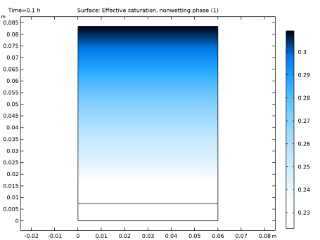
In the Settings window for 2D Plot Group, type Effective Saturation, Nonwetting Phase in the Label text field.
|
|
1
|
|
2
|
|
3
|
|
4
|
Browse to the model’s Application Libraries folder and double-click the file twophase_flow_column_air_oil.txt.
|
|
1
|
|
2
|
|
3
|
|
4
|
Browse to the model’s Application Libraries folder and double-click the file twophase_flow_column_oil_water.txt.
|
|
1
|
|
2
|
|
3
|
Select the Modify model configuration for study step checkbox.
|
|
4
|
In the tree, select Component 1 (comp1) > Definitions > Air-Oil Experiment and Component 1 (comp1) > Definitions > Oil-Water Experiment.
|
|
5
|
Right-click and choose Disable.
|
|
1
|
|
2
|
Go to the Add Study window.
|
|
3
|
|
4
|
Click the Add Study button in the window toolbar.
|
|
5
|
|
1
|
|
2
|
|
1
|
|
2
|
|
3
|
|
4
|
|
5
|
Locate the Physics and Variables Selection section. Select the Modify model configuration for study step checkbox.
|
|
6
|
In the tree, select Component 1 (comp1) > Definitions > Air-Water Experiment and Component 1 (comp1) > Definitions > Oil-Water Experiment.
|
|
7
|
Right-click and choose Disable.
|
|
8
|
|
1
|
In the Model Builder window, under Results > Datasets right-click Cut Point 2D 1 and choose Duplicate.
|
|
2
|
|
3
|
|
1
|
In the Model Builder window, right-click Inlet Air Pressure and Capillary Pressure, Air-Water and choose Duplicate.
|
|
2
|
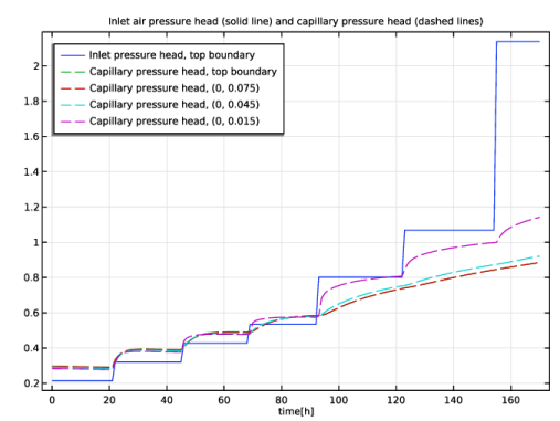
In the Settings window for 1D Plot Group, type Inlet Air Pressure and Capillary Pressure, Air-Oil in the Label text field.
|
|
3
|
|
1
|
In the Model Builder window, expand the Inlet Air Pressure and Capillary Pressure, Air-Oil node, then click Point Graph 1.
|
|
2
|
|
3
|
|
1
|
|
2
|
|
3
|
|
4
|
|
1
|
|
2
|
Go to the Add Study window.
|
|
3
|
|
4
|
Click the Add Study button in the window toolbar.
|
|
5
|
|
1
|
|
2
|
|
1
|
|
2
|
|
3
|
|
4
|
|
5
|
Locate the Physics and Variables Selection section. Select the Modify model configuration for study step checkbox.
|
|
6
|
In the tree, select Component 1 (comp1) > Definitions > Air-Water Experiment and Component 1 (comp1) > Definitions > Air-Oil Experiment.
|
|
7
|
Right-click and choose Disable.
|
|
8
|
|
1
|
In the Model Builder window, under Results > Datasets right-click Cut Point 2D 2 and choose Duplicate.
|
|
2
|
|
3
|
|
1
|
In the Model Builder window, right-click Inlet Air Pressure and Capillary Pressure, Air-Oil and choose Duplicate.
|
|
2
|
In the Settings window for 1D Plot Group, type Inlet Air Pressure and Capillary Pressure, Oil-Water in the Label text field.
|
|
3
|
|
1
|
In the Model Builder window, expand the Inlet Air Pressure and Capillary Pressure, Oil-Water node, then click Point Graph 3.
|
|
2
|
|
3
|
|
4
|