
|
|
|
|
1
|
|
2
|
|
3
|
Click Add.
|
|
4
|
Click
|
|
5
|
|
6
|
Click
|
|
1
|
|
2
|
|
1
|
|
2
|
On the object sq1, select Point 1 only.
|
|
3
|
|
4
|
|
1
|
|
2
|
Select the object fil1 only.
|
|
1
|
|
2
|
|
3
|
|
4
|
|
5
|
|
1
|
|
2
|
|
3
|
|
1
|
|
2
|
|
4
|
Locate the Selections of Resulting Entities section. Select the Resulting objects selection checkbox.
|
|
5
|
|
6
|
|
1
|
|
2
|
|
3
|
|
4
|
|
5
|
|
6
|
|
7
|
Click OK.
|
|
1
|
|
2
|
|
3
|
|
4
|
|
5
|
|
6
|
|
7
|
|
1
|
|
2
|
Go to the Add Material window.
|
|
3
|
|
4
|
Click Add to Component in the window toolbar.
|
|
5
|
|
1
|
|
2
|
|
3
|
|
1
|
|
2
|
|
3
|
|
4
|
Click to expand the Element Size Parameters section. In the Maximum element size text field, type Lmax.
|
|
5
|
|
6
|
Click
|
|
1
|
|
2
|
|
3
|
|
4
|
|
5
|
|
6
|
|
7
|
Click OK.
|
|
8
|
|
9
|
|
1
|
|
3
|
|
4
|
|
1
|
|
3
|
|
4
|
|
5
|
|
1
|
|
2
|
|
3
|
|
4
|
Locate the Coordinate System Selection section. From the Coordinate system list, choose Global coordinate system.
|
|
5
|
|
6
|
|
1
|
|
2
|
|
3
|
|
4
|
Click to expand the Preserve Continuity of Normals over Symmetry Boundaries section. From the Selection list, choose Symmetry Edge.
|
|
5
|
|
6
|
In the text field, type Lmax.
|
|
7
|
|
8
|
|
1
|
|
2
|
|
3
|
|
1
|
|
2
|
|
3
|
|
5
|
|
1
|
|
2
|
|
3
|
|
4
|
|
5
|
|
1
|
|
2
|
|
3
|
Select the Include geometric nonlinearity checkbox.
|
|
4
|
Locate the Physics and Variables Selection section. Select the Modify model configuration for study step checkbox.
|
|
5
|
|
6
|
Click
|
|
7
|
Click
|
|
8
|
|
9
|
Click
|
|
11
|
|
12
|
|
13
|
|
1
|
|
2
|
Go to the Add Study window.
|
|
3
|
|
4
|
Click Add Study in the window toolbar.
|
|
5
|
|
1
|
|
2
|
Select the Include geometric nonlinearity checkbox.
|
|
3
|
|
4
|
Click
|
|
6
|
|
7
|
|
1
|
|
2
|
|
3
|
Clear the Move limits checkbox.
|
|
4
|
|
5
|
Click Add Expression in the upper-right corner of the Objective Function section. From the menu, choose Component 1 (comp1) > Shell > Global > comp1.shell.Ws_tot - Total elastic strain energy - J.
|
|
6
|
|
7
|
|
8
|
|
1
|
|
2
|
|
3
|
|
4
|
|
5
|
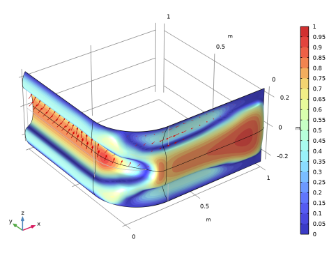
Locate the Data section. From the Dataset list, choose Study 2: Shape Optimization/Solution 2 (sol2).
|
|
1
|
|
2
|
|
3
|
|
1
|
In the Model Builder window, expand the Study 2: Shape Optimization > Solver Configurations > Solution 2 (sol2) > Optimization Solver 1 > Stationary Solver 1 > Segregated 1 node, then click Shell.
|
|
2
|
|
3
|
|
1
|
|
2
|
|
3
|
Select the Plot checkbox.
|
|
4
|
|
5
|
|
1
|
|
2
|
|
1
|
|
2
|
|
1
|
|
2
|