|
|
|
|
•
|
|
•
|
|
•
|
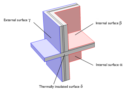
the outside, γ;
|
|
1
|
|
2
|
|
3
|
Click Add.
|
|
4
|
Click
|
|
5
|
|
6
|
Click
|
|
1
|
|
2
|
|
1
|
|
2
|
|
3
|
|
4
|
Browse to the model’s Application Libraries folder and double-click the file thermal_bridge_3d_two_floors_parameters.txt.
|
|
1
|
|
2
|
|
1
|
|
1
|
|
2
|
|
3
|
|
4
|
|
5
|
Click
|
|
1
|
|
2
|
|
3
|
|
4
|
|
5
|
Click
|
|
6
|
|
1
|
|
2
|
Click in the Graphics window and then press Ctrl+A to select both objects.
|
|
3
|
|
4
|
Clear the Keep interior boundaries checkbox.
|
|
5
|
|
1
|
|
2
|
|
3
|
|
4
|
|
5
|
|
6
|
|
7
|
Click
|
|
1
|
|
2
|
|
3
|
|
4
|
|
5
|
|
6
|
|
7
|
Click
|
|
1
|
|
2
|
|
3
|
|
4
|
Clear the Keep interior boundaries checkbox.
|
|
5
|
Click
|
|
1
|
|
2
|
|
4
|
Click
|
|
5
|
|
1
|
|
2
|
|
3
|
|
4
|
|
5
|
|
6
|
|
7
|
|
8
|
|
9
|
Click
|
|
1
|
|
2
|
Select the object ext1 only.
|
|
3
|
|
4
|
|
5
|
Select the object blk1 only.
|
|
6
|
Click
|
|
1
|
|
2
|
|
3
|
|
4
|
|
5
|
|
6
|
|
7
|
|
8
|
|
9
|
Click
|
|
1
|
|
2
|
On the object fin, select Edges 6, 17, 33, 38, 60, and 63 only.
|
|
3
|
To reach the edges, click the Wireframe Rendering button in the Graphics toolbar. Note that you can make the selection by clicking the Paste Selection button and typing the indices in the dialog that opens.
|
|
4
|
|
1
|
|
2
|
On the object ige1, select Domains 4 and 5 only.
|
|
3
|
|
1
|
|
2
|
On the object ige1, select Domain 2 only.
|
|
3
|
|
1
|
|
2
|
|
3
|
On the object ige1, select Domain 1 only.
|
|
1
|
|
2
|
|
3
|
On the object ige1, select Domain 3 only.
|
|
1
|
|
2
|
|
3
|
On the object ige1, select Domain 6 only.
|
|
1
|
|
2
|
|
3
|
|
4
|
On the object ige1, select Boundaries 33–35 only.
|
|
1
|
|
2
|
|
3
|
|
4
|
On the object ige1, select Boundaries 39–41 only.
|
|
1
|
|
2
|
|
3
|
|
4
|
On the object ige1, select Boundaries 1, 2, and 11–14 only.
|
|
1
|
|
2
|
|
3
|
|
4
|
Locate the Material Contents section. In the table, enter the following settings:
|
|
1
|
|
2
|
|
3
|
|
4
|
Locate the Material Contents section. In the table, enter the following settings:
|
|
1
|
|
2
|
|
3
|
|
4
|
Locate the Material Contents section. In the table, enter the following settings:
|
|
1
|
|
2
|
|
3
|
Locate the Geometric Entity Selection section. From the Selection list, choose Horizontal Structure.
|
|
4
|
Locate the Material Contents section. In the table, enter the following settings:
|
|
1
|
|
2
|
|
3
|
|
4
|
Locate the Material Contents section. In the table, enter the following settings:
|
|
1
|
|
2
|
|
3
|
|
4
|
|
5
|
|
6
|
|
1
|
|
2
|
|
3
|
|
4
|
|
5
|
|
6
|
|
1
|
|
3
|
|
4
|
|
5
|
|
6
|
|
7
|
|
1
|
|
2
|
|
3
|
|
4
|
Click
|
|
1
|
|
2
|
|
3
|
Click
|
|
4
|
|
5
|
Click OK.
|
|
6
|
|
8
|
Click
|
|
1
|
|
2
|
|
1
|
|
2
|
|
3
|
|
4
|
Click
|
|
1
|
|
2
|
|
3
|
|
4
|
Click
|
|
1
|
|
2
|
|
3
|
|
4
|
Click Replace Expression in the upper-right corner of the Expressions section. From the menu, choose Component 1 (comp1) > Heat Transfer in Solids > Boundary fluxes > ht.q0 - Inward heat flux - W/m².
|
|
5
|
Click
|
|
1
|
|
2
|
|
3
|
|
4
|
Click Replace Expression in the upper-right corner of the Expressions section. From the menu, choose Component 1 (comp1) > Heat Transfer in Solids > Boundary fluxes > ht.q0 - Inward heat flux - W/m².
|
|
5
|
Click
|
|
1
|
|
2
|
|
3
|
|
4
|
Click Replace Expression in the upper-right corner of the Expressions section. From the menu, choose Component 1 (comp1) > Heat Transfer in Solids > Boundary fluxes > ht.q0 - Inward heat flux - W/m².
|
|
5
|
Click
|
|
1
|
Go to the Table 5 window.
|
|
1
|
|
2
|
|
3
|
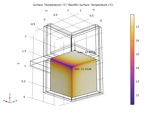
In the Settings window for 3D Plot Group, type Minimum Temperature on Alpha in the Label text field.
|
|
4
|
|
5
|
|
1
|
|
2
|
|
3
|
|
1
|
|
2
|
|
3
|
|
1
|
|
2
|
|
3
|
|
4
|
|
5
|
Click
|
|
1
|
|
2
|
|
3
|
|
4
|
|
5
|
|
1
|
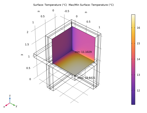
In the Model Builder window, expand the Results > Minimum Temperature on Beta > Surface 1 node, then click Selection 1.
|
|
2
|
|
3
|
|
1
|
In the Model Builder window, expand the Results > Minimum Temperature on Beta > Max/Min Surface 1 node, then click Selection 1.
|
|
2
|
|
3
|
|
4
|
|
5
|