Theory for Single-Port Components
The equations for all the single-port components, which are also known as the terminals, are described below:
•
Theory for Free node
•
Theory for Fixed Node
•
Theory for Displacement Node
•
Theory for Velocity Node
•
Theory for Acceleration Node
•
Theory for Mass node
•
Theory for Force Node
•
Theory for Impedance Node
Theory for Free node
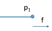
Figure 5-8:
A free node connected at node p1.
The following equation prescribes the nodal force,
f
p
1
:
Theory for Fixed Node
Figure 5-9:
A fixed node connected at node p1.
The following equation prescribes the node displacement,
u
p
1
:
Theory for Displacement Node
Figure 5-10:
A displacement node connected at node p1.
The following equation prescribes the node displacement,
u
p
1
:
Frequency-Domain and Eigenfrequency Studies
Time-Dependent and Stationary Studies
Here
u
p
10
is the prescribed displacement value and
ϕ
is the phase angle.
Sometimes, a parallel-connected spring–damper system with one end fixed and the other end prescribed using a
Displacement Node
shows convergence issues. For such cases, try one of the following alternatives:
•
Use a
Velocity Node
instead of a
Displacement Node
to prescribe the equivalent velocity at the end.
•
Increase the scaling of force variables if the automatic scaling estimate is too small.
•
For time dependent studies, modify the time-dependent solver settings by setting
Error estimation
in the
Time Stepping
section to
Exclude algebraic
.
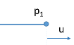
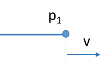
Theory for Velocity Node
Figure 5-11:
A velocity node connected at node p1.
The following equation prescribes the node displacement,
u
p
1
, given that
v
p
1
is the prescribed velocity value:
Frequency-Domain and Eigenfrequency Studies
Time-Dependent Studies
Stationary Studies
If the displacement is set to free:
If the displacement is set to constrained:
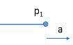
Theory for Acceleration Node
Figure 5-12:
An acceleration node connected at node p1.
The following equation prescribes the node displacement,
u
p
1
, given that
a
p
1
is the prescribed acceleration value:
Frequency-Domain and Eigenfrequency Studies
Time-Dependent Studies
Stationary Studies
If the displacement is set to free:
If the displacement is set to constrained:
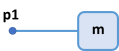
Theory for Mass node
A mass node adds a lumped mass to a node in the mechanical system.
Figure 5-13:
A mass node connected at node p1.
The following equations are used to relate force (
f
), mass (
m
) and displacement (
u
) of the component:
Frequency-Domain and Eigenfrequency Studies
Time-Dependent Studies
Stationary Studies
An additional gravity force is added in the component force when the gravity contribution is included:
Theory for Force Node
Figure 5-14:
A force node connected at node p1.
The following equation prescribes the nodal force,
f
p
1
:
Frequency-Domain and Eigenfrequency Studies
Time-Dependent and Stationary Studies
Here
f
p
10
is the prescribed force value and
ϕ
is the phase angle.
Theory for Impedance Node
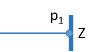
Figure 5-15:
An impedance node connected at node p1.
The following equation relates the nodal force (
f
p
1
) and node displacement (
u
p
1
):
Frequency-Domain and Eigenfrequency Studies
Time-Dependent and Stationary Studies
Here
Z
is the prescribed impedance value.