|
|
|
|
|
|
|
|
||
|
|
|||
|
|
|
||
|
|
|
|
•
|
In 2D components, select between Plane symmetry (default), Two perpendicular symmetry planes, or Sector symmetry.
|
|
•
|
In 2D axisymmetric components, only the Plane symmetry option is available.
|
|
•
|
In 3D components, select between Plane symmetry (default), Two perpendicular symmetry planes, Three perpendicular symmetry planes, or Sector symmetry.
|
|
•
|
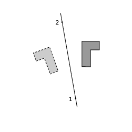
In 2D components, the symmetry plane is defined by two points. If the Selection method is Coordinates, set the x and y coordinates of the First point defining reflection plane and of the Second point defining reflection plane. Else, if the Selection method is Point selection, you can directly select the points from the Graphics window. In the First Point Defining Reflection Plane and Second Point Defining Reflection Plane sections, first use the Active button to toggle between turning ON
|
|
•
|
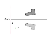
In 2D axisymmetric components, the symmetry plane is parallel to the z=0 plane. If the Selection method is Coordinates, set the Reflection plan position, zsym. Else, if the Selection method is Point selection, you can directly select the point from the Graphics window. In the First Point Defining Reflection Plane section, first use the Active button to toggle between turning ON
|
|
•
|
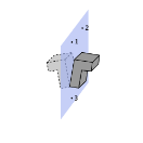
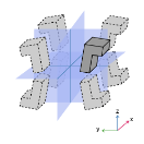
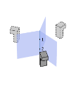
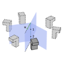
In 3D components, the symmetry plane is defined by three points. If the Selection method is Coordinates, set the x, y, and z coordinates of the First point defining reflection plane, the Second point defining reflection plane, and the Third point defining reflection plane. Else, if the Selection method is Point selection, you can directly select the points from the Graphics window. In the First Point Defining Reflection Plane, Second Point Defining Reflection Plane, and Third Point Defining Reflection Plane sections, first use the Active button to toggle between turning ON
|
|
•
|
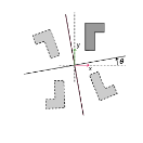
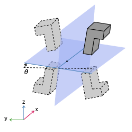
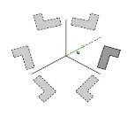
In 2D components, the planes intersection line is along the out-of-plane direction. The Point at intersection of symmetry planes and the Rotation angle from Cartesian axis, θ, should be defined. If the Selection method is Coordinates, set the x and y coordinates of the Point at intersection of symmetry planes. Else, if the Selection method is Point selection, you can directly select the point from the Graphics window. In the Point at Intersection of Symmetry Planes section, first use the Active button to toggle between turning ON
|
|
•
|
In 3D components, the Planes intersection line can be set Along the x-axis, Along the y-axis, or Along the z-axis. A Point the intersection of symmetry planes and the Rotation angle from Cartesian axis, θ, should be defined. If the Selection method is Coordinates, set the x, y, and z coordinates of the Point at intersection of symmetry planes. Else, if the Selection method is Point selection, you can directly select the point from the Graphics window. In the Point at Intersection of Symmetry Planes section, first use the Active button to toggle between turning ON
|
|
•
|
In 2D components, the symmetry axis is the out-of-plane vector, and the center of the symmetry must be defined. If the Selection method is Coordinates, set the x and y coordinates of the Point defining central symmetry. Else, if the Selection method is Point selection, you can directly select the point from the Graphics window. In the Point Defining Central Symmetry section, first use the Active button to toggle between turning ON
|
|
•
|
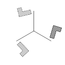
In 3D components, the symmetry axis is defined by two points. If the Selection method is Coordinates, set the x, y, and z coordinates of the First point defining sector symmetry axis and of the Second point defining sector symmetry axis. Else, if the Selection method is Point selection, you can directly select the points from the Graphics window. In the First Point Defining Sector Symmetry Axis and Second Point Defining Sector Symmetry Axis sections, first use the Active button to toggle between turning ON
|
|
|