Geometry 1
First import parameters that will be used in the model set up.
Note: The exact location of the files used in this exercise may vary based on the installation. For example, if the installation is on your hard drive, the file path might be similar to C:\Program Files\COMSOL\COMSOL63\Multiphysics\applications\Heat_Transfer_Module\Tutorials,_Forced_and_Natural_Convection\
1
2
In the Settings window for Parameters, locate the Parameters section.
3
Click Load from File 
4
5
In the Geometry toolbar, click Block .
6
In the Settings window for Block, locate the Size and Shape section.
7
In the Width text field, type L_chip.
8
In the Depth text field, type L_chip.
9
In the Height text field, type H_chip.
10
Locate the Position section. In the z text field, type -H_chip.
11
Click Build Selected .
12
13
14
15
16
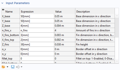
In the Settings window for Part Instance, locate the row for the parameter n_fins_x in the Input Parameters section and enter n_fins as value expression. Then define X_fins_bottom and X_fins_top to 3[mm] and 2[mm]respectively.
17
18
In the Displacement subsection, type -5[mm] in the xw and yw text fields.
19
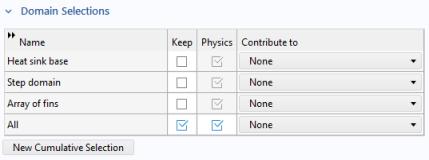
Click to expand the Domain Selections section. For row number 4 labeled All in the table, click to select the Keep checkbox to make the domain selection available in the physics interfaces. This selection corresponds to all the geometrical domains of the heat sink.
20
21
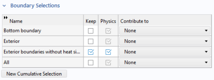
Click to expand the Boundary Selections section. For row number 3 labeled Exterior boundaries without heat sink base in the table, click to select the Keep checkbox.
22
23
24