To create a lofted object from a set of profiles in 3D, in the Geometry toolbar, click
Loft (

). You can also right-click the
Geometry node and add this node from the context menu. Enter the properties of the loft operation according to the following sections.
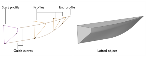
Select the objects that you want to use as profiles in the Graphics window. You can select a set of connected surface objects, curve objects, or point objects. Surface objects must have manifold topology and be bounded by a single edge loop. Curve objects must be a single edge loop or chain. Point objects are only allowed for use as start or end profiles and must have a single vertex. The selected objects appear in the
Profile objects list. If the geometry sequence includes user-defined selections above the
Loft node, choose
Manual to select objects, or choose one of the selection nodes from the list next to
Profile objects.
Click the Active button to toggle between turning ON and OFF the
Profile objects selection.
Select a Geometric entity level for the profile —
Object,
Point,
Edge, or
Boundary. Click to select the entities in the
Graphics window. An object selection must fulfill the requirements detailed in the
Profiles section. A point selection must consist of a single point. An edge selection must form a single edge loop or chain. A boundary selection must have manifold topology and be bounded by a single edge loop. The selected entities appear in the
Start profile list. If the geometry sequence includes user-defined selections above the
Loft node, choose
Manual to select objects or entities, or choose one of the selection nodes from the list next to
Input objects.
Click the Active button to toggle between turning ON and OFF the
Start profile selection.
Select a Loft direction —
Not prescribed (the default),
Parallel,
Perpendicular, or
At angle. For
Parallel the loft direction is prescribed along the profile curve, while for
Perpendicular or
At angle it is only prescribed at the vertices on the profile curve.
Select Relative to —
Adjacent faces (the default),
Profile faces, or
Profile edges’ plane. When
At angle is selected, also enter an
Angle (SI unit: deg).
Select the objects that you want to use as guides in the Graphics window. You can select a set of curve objects. In the nonperiodic case, each guide object must be a single edge chain. In the periodic case, each guide object must be a single edge loop. Each guide object must have continuous tangents and intersect each profile exactly once. The objects appear in the
Guide objects list. If the geometry sequence includes user-defined selections above the
Loft node, choose
Manual to select objects, or choose one of the selection nodes from the list next to
Guide objects.
Click the Active button to toggle between turning ON and OFF the
Guide objects selection.
Select a Loft surface direction —
Not prescribed (the default) or
Parallel to adjacent faces, which means that the loft surface is prescribed to be tangent to the adjacent faces along the guide curve.
If you want to make the resulting entities contribute to a cumulative selection, select a cumulative selection from the Contribute to list (the default,
None, gives no contribution), or click the
New button to create a new cumulative selection (see
Cumulative Selections in the
COMSOL Multiphysics Reference Manual).
Select the Resulting objects selection checkbox to create predefined selections (for all levels — objects, domains, boundaries, edges, and points — that are applicable) in subsequent nodes in the geometry sequence. To also make all or one of the types of resulting entities (domains, boundaries, edges, and points) that the resulting objects consist of available as selections in all applicable selection lists (in physics and materials settings, for example), choose an option from the
Show in physics list:
All levels,
Domain selection,
Boundary selection,
Edge selection, or
Point selection. The default is
Domain selection, which is suitable for use with materials and physics defined in domains. For use with a boundary condition, for example, choose
Boundary selection. These selections do not appear as separate selection nodes in the model tree. Select
Off to not make any selection available outside of the geometry sequence.
If you have Named Selections that include entities on the input objects, select the
Propagate selections to resulting objects (selected by default) checkbox to update the selections to corresponding entities on the output objects, when possible. Clear the checkbox to not propagate the selection to the resulting objects. Selecting this option can be useful in combination with clearing the
Unite with input objects checkbox so that the selections refer only to the input objects.
From the Construction geometry list choose
On to make the resulting objects available only in the feature’s geometry sequence. The default option
Inherit from input means that the resulting objects become construction geometry if all input objects are construction geometry. Choose
Off to never output construction geometry objects. For more information see
Construction Geometry in the
COMSOL Multiphysics Reference Manual.