Fillet
To fillet corners in 3D geometry objects, from the Geometry toolbar, Editing () menu, select Fillet (). You can also right-click the Geometry node and add this node from the context menu.
Type of Fillet
Select a Type for the fillet — Constant radius (the default), Constant width, or Variable radius.
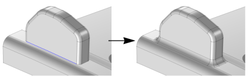
For Constant radius, the fillet surface is generated by rolling a ball of the given radius so that it is tangent to the faces adjacent to the edge. When you build the feature, the faces adjacent to the selected edges are shrunk and a fillet face is inserted in between.
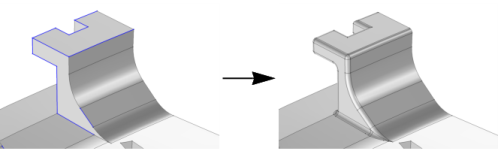
For Constant width, the fillet face is generated in a way that the distance between the two edges that separate the fillet face from the adjacent faces is constant.
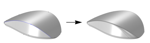
For Variable radius, you can specify the radius at chosen locations along the selected edges. The fillet radius is then interpolated between the given radius values.
For all fillet types, when more than two selected edges meet at a vertex, one or several additional patch faces are inserted at the vertex to get a smooth result. If the radius is large, it can happen that the fillet face overflows the original faces. In this case the fillet face meets other, more distant, faces in the object.
Edges
Select the edges that you want to fillet in the Graphics window. They then appear in the Edges to fillet list. If the geometry sequence includes user-defined selections above the Fillet node, choose Manual to select edges, or choose one of the selection nodes from the list next to Edges to fillet.
Click the Active button to toggle between turning ON and OFF the Edges to fillet selections.
To automatically extend the selection to tangent edges select the Group by continuous tangent checkbox (cleared by default). Modify the Angular tolerance to control which edges are added to the selection. Values between 0 and 180 degrees are supported (default: 5 degrees).
The objects containing the selected edges must have manifold topology in the neighborhood of the selected edges. In particular, each edge must be adjacent to exactly two faces. For Variable radius, you can only select edges from a single geometry object.
Radius
This section is displayed when Type is set to Constant radius. Enter the Radius of the fillet (SI unit: m). The fillet surface is generated by rolling a ball of the given radius so that it is tangent to the faces adjacent to the edge.
Width
This section is displayed when Type is set to Constant width. Enter the Width of the fillet (SI unit: m). The width of the fillet is the distance between the two edges that separate the fillet face from the adjacent faces.
Radii
This section is displayed when Type is set to Variable radius. Use the table to specify the radii at locations given by parameter values along the selected edges.
The Edge column displays the edge numbers for the selected edges. When you select a row in the table the corresponding edge is highlighted in the Graphics window.
In the Parameter column enter the relative arc length parameter where the radius is specified along an edge. The parameter can have values between 0 (at the start vertex of the edge) and 1 (at the end vertex of the edge). See the direction arrows displayed in the Graphics window for determining the edge orientations.
In the Radius column enter the value for the radius to be applied at the location along the edge specified by the parameter. The radius value can be a positive number or 0. An empty cell (the default) means that the radius is not defined, and that the row for the corresponding location is ignored when creating the fillet.
Select the checkbox (cleared by default) in the Clamp column to constrain to zero the derivative of the fillet radius with respect to the relative arc length parameter at this point along the edge.
Below the table, click the Insert Above () or Insert Below () button to add rows to the table for specifying radius values at additional locations along an edge. Select a row and click Delete () to remove it from the table. Only rows that do not correspond to the first and last points of an open ended chain are possible to delete. You can also leave a radius field empty to ignore a row when creating the fillet.
Click List All Fillet Edges () to insert one row for each fillet edge that is missing from the table, and to sort the table. The Delete Rows Without Radius () button is useful to compact the table in case there are many rows with empty radius values. Rows that correspond to the first and last points of an open edge chain are not deleted since you need to specify a radius for these. For a better overview of the specified radius values click the Sort Edge Chains () button. The table is then sorted primarily on the edge chains, secondly on the natural order of the edges, and thirdly on the parameters in the chain’s direction.
Options
Select or clear the following checkboxes as needed.
If the Propagate to tangent edges checkbox is selected, the fillet is propagated to edges that have continuous tangent to the edges selected in Edges to fillet. This checkbox is available only when Type is Constant radius or Constant width.
If the Preserve overlapped entities checkbox is selected, geometric features such as holes and bosses on faces that are overlapped by the fillet surface are preserved.
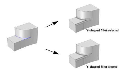
Select the Y-shaped fillet checkbox to get a y-shaped fillet at a vertex where three or more edges meet and there are two fillet surfaces of different convexity. This option is not available when the fillet Type is Constant width. In some cases, using this option is necessary for the operation to succeed.
Select the Fillet sharp edges at vertices checkbox to get a smooth fillet surface at vertices where two filleted edges intersect at an angle. This option is not available when the fillet Type is Constant width.
Selections of Resulting Entities
If you want to make the resulting entities contribute to a cumulative selection, select a cumulative selection from the Contribute to list (the default, None, gives no contribution), or click the New button to create a new cumulative selection (see Cumulative Selections in the COMSOL Multiphysics Reference Manual).
Select the Resulting objects selection checkbox to create predefined selections (for all levels — objects, domains, boundaries, edges, and points — that are applicable) in subsequent nodes in the geometry sequence. To also make all or one of the types of resulting entities (domains, boundaries, edges, and points) that the resulting objects consist of available as selections in all applicable selection lists (in physics and materials settings, for example), choose an option from the Show in physics list: All levels, Domain selection, Boundary selection, Edge selection, or Point selection. The default is Domain selection, which is suitable for use with materials and physics defined in domains. For use with a boundary condition, for example, choose Boundary selection. These selections do not appear as separate selection nodes in the model tree. Select Off to not make any selection available outside of the geometry sequence.
Assigned Attributes
From the Construction geometry list choose On to make the resulting objects available only in the feature’s geometry sequence. The default option Inherit from input means that the resulting objects become construction geometry if all input objects are construction geometry. Choose Off to never output construction geometry objects. For more information see Construction Geometry in the COMSOL Multiphysics Reference Manual.