Physics Nodes — Equation Section
For each physics node there is an Equation section that is available by default in the Settings window. This section has options to display mathematical equations applicable to the node.
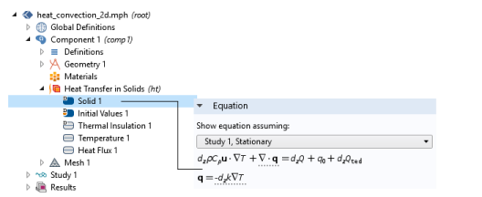
If you do not want to display the Equation section, click the Show More Options button () and clear the Equation Sections checkbox in the Show More Options dialog.
The display options available from the lists depend on the study types and other physics-specific factors. See Figure 3-20 for an example comparing the equations that display for a Stationary or Time Dependent study for a Heat Transfer in Solids interface.
Node Contributions Display a Dotted Line Under Part of the Equation
For all physics nodes (excluding the main physics interface node level), the equation that displays includes a dotted line underneath where the node’s contribution is made to the equation. See Figure 3-19 for an example where a section of the heat transfer equation is underlined, indicating where the Solid node contributes to it.
Figure 3-19: The Solid contribution to the equation for a 2D model.
Show Equation Assuming
The Show equation assuming list is available when the parent interface’s Equation form setting is Study controlled. Otherwise equations are displayed for the selected equation form (see Equation Form Settings). When the equation form is controlled by the study, the list lets you choose between all available study steps. The equations below will be displayed for the equation form that is automatically selected for the selected study step.
Figure 3-20: An example of the Equation section on a Heat Transfer interface. Selecting the study type updates the equation accordingly.
The None option is only available for features which do not have a parent with an equation form setting, for example optimization features.
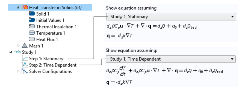
The chosen option in the Show equation assuming list only affects the displayed equations. It does not affect the computed solution in any way.