|
|
See the Learning Center resource Using Swept Meshes for Model Geometries for more examples and animations: https://www.comsol.com/support/learning-center/article/48941/152
|
|
|
See The Mesh Node for more information about meshes that define their own geometric models.
|
|
•
|
|
•
|
|
•
|
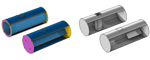
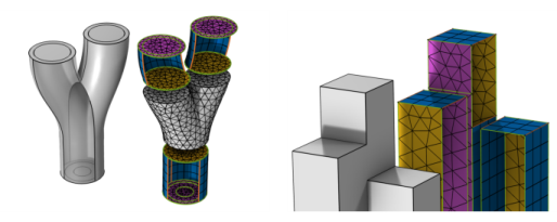
Each source face must correspond to precisely one destination face or a subset of it (see Figure 8-103 and Figure 8-106). If needed, use a Cross Section operation to make an imprint of the source faces on the destination.
|
|
•
|
|
•
|
|
•
|
|
•
|
Choose Remaining to generate a swept mesh for the remaining, unmeshed domains.
|
|
•
|
Choose Entire geometry to specify swept mesh for the entire geometry.
|
|
•
|
Choose Domain to specify the domains for which you want a swept mesh. Choose Manual in the Selection list to select the domains in the Graphics window, choose a named selection to refer to a previously defined selection, or choose All domains to select all domains.
|
|
•
|
Select Automatic (prefer hexahedra) to let the algorithm select a suitable face meshing method (default). It tries to generate a quadrilateral mesh and switches to triangular if it fails or if the element quality becomes to low. The source faces are allowed to have different element types, which means that the resulting mesh can contain a mixture of hexahedral and prism elements, also in the same domain.
|
|
•
|
Select Quadrilateral (generate hexahedra) to generate a surface mesh with quadrilateral elements.
|
|
•
|
Select Triangular (generate prisms) to generate a surface mesh with triangular elements.
|
|
•
|
The default, Automatic, means that the sweeping algorithm automatically tries to determine if the sweep path is straight or circular; otherwise, a general approach is used.
|
|
•
|
Sweep following straight lines means that all interior mesh vertices are located on straight lines between the corresponding source and destination points.
|
|
•
|
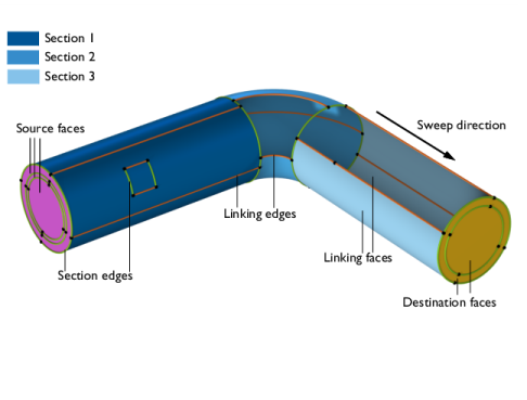
Sweep following circular arcs means that all interior mesh vertices are located on circular arcs between the corresponding source and destination points, as shown in Figure 8-102.
|
|
•
|
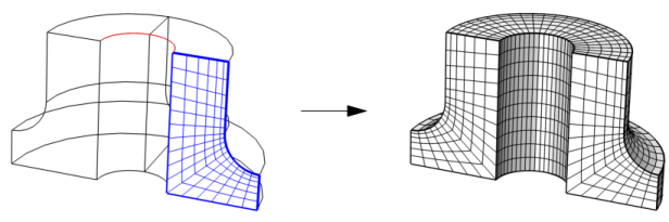
Sweep using interpolation means that the positions of the interior mesh vertices are determined by a general interpolation procedure, as shown in Figure 8-108.
 |
|
•
|
The default, Determine suitable method, means that the algorithm automatically tries to determine a suitable method for creating the destination mesh.
|
|
•
|
Use a rigid transformation when the source and destination have the same shape, up to a scaling factor.
|
|
•
|
Morph source onto destination when the source and destination have different shape. For example, when going from a circular to a rectangular cross-section, or going from a planar source face to a curved destination face.
|
|
•
|
Project source mesh onto destination means that the destination mesh is created from the source mesh by a projection technique. This is useful when the source and destination faces are close to each other and have different shape.
|
|
|
|
|
|
|