A Graphics Data declaration node is used to pick data at a specific coordinate from a graphics object based on mouse clicks by the user. The figure below shows the corresponding
Settings window.
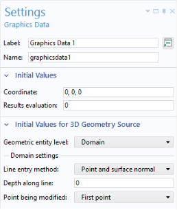
The Initial Values section contains default values for the extracted data properties
Coordinate and
Results evaluation. The section
Initial Values for 3D Geometry Source contains settings for the selection methods available when the
Source for Initial Graphics Content of a graphics object is set to a geometry node.
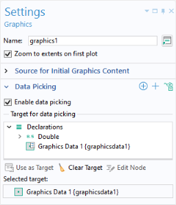
To use a Graphics Data declaration node for data picking, select the
Data picking checkbox in the
Settings window of a graphics object and select the
Graphics Data node as the
Target for Data Picking, as shown in the figure below.
When the Source for Initial Graphics Content of a graphics object is set to a plot group node, then the
Results Evaluation value corresponds to the field value at the position determined by the mouse pointer. The
Coordinate value corresponds to the coordinate at that position. Note that in the Model Builder, this corresponds to the data displayed in the
Evaluation 2D or
Evaluation 3D tables.
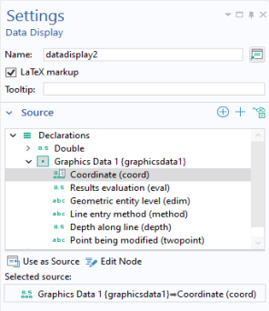
You can also use the Coordinate property as the
Source for an array input object. The
Results Evaluation property can be used as the
Source for several form objects including data display and input field objects.
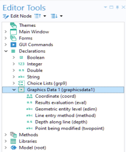
You can explore this syntax in the Editor Tools window. For example, right-click
Graphics Data 1 >
Coordinate and select
Get from the context menu.
The settings Geometry Entity Level,
Line Entry Method,
Depth Along Line, and
Point Being Modified only apply when the
Source for Initial Graphics Content of a graphics object is set to a 3D geometry node. These settings provide the same point selection methods as a
Domain Point Probe, when
Geometry Entity Level is set to
Domain; and
Boundary Point Probe, when
Geometry Entity Level is set to
Boundary. The settings
Line Entry Method,
Depth Along Line, and
Point Being Modified are only applicable when
Geometry Entity Level is set to
Domain.