Defining a Layer Local System
Each layer in the composite laminate has different material orientations defined by the rotation angle and the laminate coordinate system. The rotation angle of each layer is defined in the Single Layer Material or Layered Material node. The Layer Local System is then created by rotating the laminate coordinate system in the reference plane by this rotation angle.
Some examples of layer local coordinate systems in a cylindrical composite laminate having different stacking sequences, are given below.
Some examples of layer local coordinate systems in a cylindrical composite laminate, using different stacking sequences, are given below.
Example 1
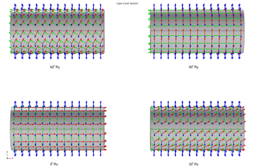
The stacking sequence of a composite laminate is [0/30/60/90]. The first axis of the laminate coordinate system is aligned with the global x direction. This can be created by setting the Create first tangent direction from option to Global Cartesian (spatial), and by setting the Axis to x.
.
Figure 2-13: Example of a layer local coordinate system in different plies. The first axis of the laminate coordinate system is the global x direction.
Example 2
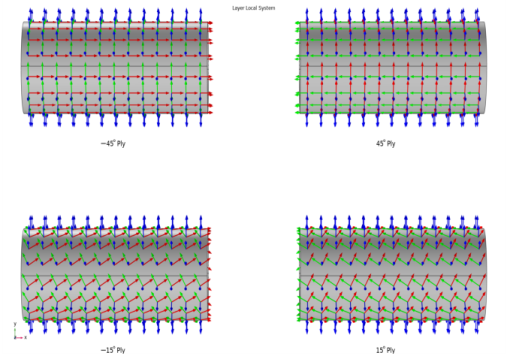
The stacking sequence of a composite laminate is [-15/15/-45/45]. The first axis of the laminate coordinate system is at 45° to the global x direction. This can be created by defining a Cylindrical System having Longitudinal axis as x-axis. Then set the Create first tangent direction from to Cylindrical System and the Axis to Manual with {0,-1,1} as the orientation.
Figure 2-14: Example of a layer local coordinate system in different plies. The first axis of the laminate coordinate system is at 45° with respect to the global x direction.
Example 3
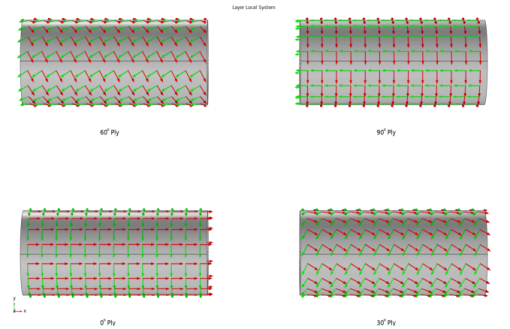
The stacking sequence of a composite laminate is [0/30/60/90]. The first axis of laminate coordinate system is aligned with the global x direction but with the normal direction pointing inward. This coordinate system can be created in a same way as in the first example. In addition to that, the Reverse Normal direction option is selected in the Boundary System node in order to flip the normal vector.
Figure 2-15: Example of a layer local coordinate system in different plies. The first axis of the laminate coordinate system is the global x direction, and the normal vector is pointing inward the cylinder.