Vacuum Pump Boundary Condition
Vacuum pumps (devices) can be represented using lumped curves implemented as boundary conditions. These simplifications also imply some assumptions. In particular, it is assumed that a given boundary can only be an outlet. Such a boundary should not be a mix of inlets/outlets nor switch between them during a simulation.
Manufacturers usually provide curves that describe the pumping rate as a function of suction pressure for a vacuum pump. Also see Vacuum Pump for the node settings.
Defining a Device at an Outlet
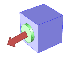
In this case (see Figure 3-2), the device’s inlet is the interior face situated between the blue (cube) and green (circle) domains while its outlet is an external boundary, here the circular boundary of the green domain. The lumped curve gives the pumping rate as a function of the pressure at the suction side of the vacuum pump. This boundary condition implementation follows the Fully Developed Flow (Outlet) boundary condition with the Flow Rate option:
(3-41)
Here, V0 is the pumping rate function of suction pressure for the vacuum pump. In 2D the thickness in the third direction, Dz, is used to define the flow rate. Vacuum pumps are modeled as rectangles in this case.
Figure 3-2: A vacuum pump at the outlet. The arrow represents the flow direction, the green circle represents the vacuum pump (that should not be part of the model), and the blue cube represents the modeled domain with an outlet boundary condition described by a lumped curve for the attached vacuum pump.