The theory of laminated shells is discussed in this section. The Linear Elastic Material, Layered node in the Shell interface allows the modeling of laminated shells, also popularly known as composite laminates, having different orthotropic properties per layer. The first order shear deformation theory (FSDT) is used to find homogenized equivalent material properties of a composite laminate.
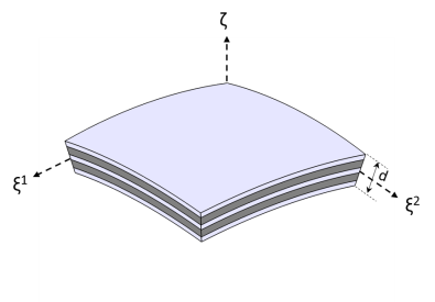
Figure 5-4 shows a doubly curved laminated shell with uniform total thickness,
d. It is represented by orthogonal curvilinear coordinate system (
ξ1, ξ2, ζ). The geometry representation of a layered shell is same as a single layer shell as discussed in the
Geometry and Deformation section.
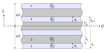
A typical stacking sequence of a composite laminate having n layers is shown in
Figure 5-5. The thickness of each layer (
dk), as well as the fiber direction in each layer (
θk) with respect to the first principal direction (
ξ1) of the laminate are indicated. A counterclockwise rotation of the fiber direction with respect to the
ζ direction is considered as positive.

In classical laminate theory, a lamina is assumed to be in a plane stress state and all three transverse stress components (σxz, σyz, σzz) are assumed to be zero. In terms of strains, the transverse shear strain components (
εxz, εyz) are zero while the transverse normal strain (
εzz) is nonzero but not part of the formulation.
The principal material direction (or fiber direction) in each lamina makes an angle (θ) with the first in-plane direction (
ξ1) of the laminate coordinate system. Hence the transformation matrix can be defined as:
For n number of layers in a laminate, there are
n+2 variables (unknowns) and thus
n+2 equations are needed to solve them. The first
n+
1 equations are the form of shear stress continuity can be written as:

