|
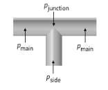
The T-junction is intended for a point that is connected to exactly two collinear main branches and one perpendicular side branch. If this condition is not met, a warning message will be issued when solving. The flow can go in either direction through each of the main branches and the side branch. See Figure 2-1.
|
|
•
|
The Loss coefficients option allows you to enter a value or expression for the Loss coefficient main branch Kmain for the energy loss between main branch and junction (the default is 0.1) and the Loss coefficient side branch Kside for the energy loss between the side branch and junction (the default is 1.2). Both are dimensionless numbers. See Figure 2-1.
|
|
•
|
The Loss coefficient with respect to common branch option is available for the Pipe Flow interface. The loss coefficients are calculated automatically. The pressure loss between the branches is expressed in terms of the flow variables in the common branch. For joining flows, the common branch is the collector branch. For separating flow, the common branch is the supplier branch.
|
|
•
|
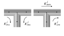
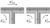
The Loss coefficients, extended model option is available for the Pipe Flow interface. This option allows you to specify the loss coefficient in more details and account for the flow directions. Enter values or expressions for the six dimensionless loss coefficients. See Figure 2-2-Figure 2-3.
 |

|
•
|
Use the Pressure drops option to specify a value or expression for the pressure drop explicitly for each branch respectively:
|