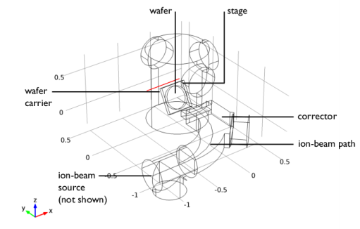
This example shows how to model an ion implantation system using the Free Molecular Flow interface. The model geometry is shown in Figure 7. The wafer is positioned on a carrier plate that is rotated about an axis through its center to achieve different implant angles. The carrier plate is mounted in a chamber that is pumped by three large cryopumps, located on cylindrical vacuum ports. These pumps have a pump speed of 12,000 l/s. In this model, outgassing of only one species from the wafer (H
2) is considered: multiple species can be added in the Dependent Variables section the Free Molecular Flow settings window. It is assumed that the outgassing across the wafer surface is uniform and that the total gas emitted is 30 sccm. The vacuum path through the corrector magnetic field enters the main chamber opposite the wafer. The corrector is pumped by a turbomolecular pump on a cylindrical port halfway along the beam path (pump speed: 1500 l/s), and an additional cryopump at the start of the beam path (pump speed: 12,000 l/s). There is an aperture at the entrance to the chamber that reduces the flux entering the corrector. The angle between the wafer outward normal and the ion beam is swept from 0
° to 60
° in 20
° steps, as the wafer is rotated about the horizontal axis through its center, as shown in
Figure 7. All other surfaces in the model are walls. Since the interaction of the outgassing molecules with the beam produces undesirable species, the average number density of the molecules along the beam path is used as a figure of merit to evaluate the effect of rotating the wafer.