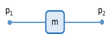
The following equations are used to relate force (fp1) and displacement (
up1) of one node to the force (
fp2) and displacement (
up2) of another node:
where f and
u are the force and displacement variables in the component. They are related by the following equations, where
m is the component mass:
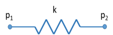
The following equations are used to relate force (fp1) and displacement (
up1) of one node to the force (
fp2) and displacement (
up2) of another node:
where f and
u are the force and displacement variables in the component. They are related by the following equation:
where k is the spring constant and
u0 is the predeformation.
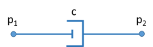
The following equations are used to relate force (fp1) and displacement (
up1) of one node to the force (
fp2) and displacement (
up2) of another node:
where f and
u are the force and displacement variables in the component. They are related by the following equations, where
c is the damping coefficient:
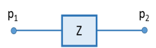
The following equations are used to relate force (fp1) and displacement (
up1) of one node to the force (
fp2) and displacement (
up2) of another node:
where f1,
f2 and
u1,
u2 are the force and displacement variables in the component. They are related by the following equations:
Here Z11,
Z12,
Z21, and
Z22 are the components of the impedance matrix.
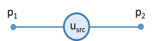
The following equations are used to relate force (fp1) and displacement (
up1) of one node to the force (
fp2) and displacement (
up2) of another node:
where f and
u are the force and displacement variables in the component. The following equation prescribes the component displacement,
u:
Here usrc is the prescribed displacement value and
ϕ is the phase angle.
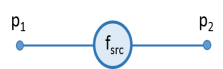
The following equations are used to relate force (fp1) and displacement (
up1) of one node to the force (
fp2) and displacement (
up2) of another node:
where f and
u are the force and displacement variables in the component. The following equation prescribes the component force,
f:
Here, fsrc is the prescribed force value and
ϕ is the phase angle.
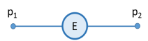
The following equations are used to relate force (fp1) and displacement (
up1) of one node to the force (
fp2) and displacement (
up2) of another node:
where f1,
f2 and
u1,
u2 are the force and displacement variables in the component. The following equation prescribes the component displacement (
u1,
u2)
where up10 and
up20 are the displacement values obtained from the component level model.
The component force (f1,
f2) obtained from the external source node of the system level model can be applied in the component level model as a feedback in order to complete the coupling between the two.