You are viewing the documentation for an older COMSOL version. The latest version is available here.
The Fatigue Interface
The Fatigue (ftg) interface (), found under the Structural Mechanics branch () when adding a physics interface, is used for fatigue evaluation based on stress, strain, or energy results computed by other structural mechanics interfaces. Using this physics interface, you can compute the risk of fatigue cracks to occur as an effect of repeated loading in a structure where the stress and strain state has been computed using one of the following physics interfaces — Solid Mechanics; Shell; Plate; Membrane; Multibody Dynamics (which requires the Multibody Dynamics Module); Solid Rotor; and Solid Rotor, Fixed Frame (the two latter require the Rotordynamics Module). The stress and strain state can be either the result of a single, deterministic load cycle, the response from a frequency sweep, or it can be a random (nondeterministic) load cycle, based on results from a random vibration analysis.
You can perform the following evaluations:
Stress Life analysis for high-cycle fatigue. The result is a lifetime prediction in terms of the number of cycles to fatigue.
Strain Life analysis for low-cycle fatigue. The result is a lifetime prediction in terms of the number of cycles to fatigue.
Stress Based analysis for high-cycle fatigue. The result is a usage factor, which tells you how close to the fatigue limit the load cycle is.
Strain Based analysis for low-cycle fatigue. The result is a lifetime prediction in terms of the number of cycles to fatigue.
Energy Based analysis when the dissipated energy controls crack formation and growth. The results are a lifetime prediction in terms of the number of cycles to failure and a dissipated fatigue energy density.
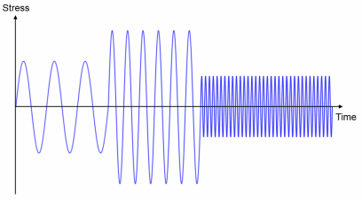
Cumulative Damage analysis for variable load history. The results are a usage factor, a stress distribution, and a fatigue usage distribution. The last two parameters present an overview of the stress variation in the load history and how damaging different cycles are. The usage factor is a relation between an accumulated damage and a damage that causes fatigue. The distribution variables are visualized with the Matrix Histogram Plot in 2D.
Harmonic Vibration analysis for frequency domain results. Typically, a frequency sweep is made, and it is assumed that the rate of change in frequency is small enough to make the response at any frequency to be considered as steady state. The result is a usage factor, which is a relation between an accumulated damage and a damage that causes fatigue.
Random Vibration analysis for structures undergoing random vibrations. The results from this analysis type is a lifetime prediction in terms of the fatigue usage factor during a time period, the damage accumulated per unit time, or the total time to failure.
Deterministic Load Cycles
A fatigue analysis requires a load cycle simulation. In a fatigue study each load event of the load cycle is processed in search for the fatigue controlling quantities. Each fatigue model depends on different quantities and you should consider whether or not a certain fatigue evaluation is suitable for a given load cycle. Load cycles can be roughly be divided into the following cases:
Proportional loading is a situation where the orientation of the principal stresses and strains does not change during a load cycle. This can be described by a load event that increases to a certain level followed be a decrease to the initial load level. The Stress Life Models, and the Strain Life Models can be used for this type of loading. Also the Stress Based Fatigue Models, the Strain Based Fatigue Models, and the Cumulative Damage Model can be used although they are intended for more general types of loading.
In nonproportional loading the directions of principal stresses and strains vary during the load cycle and special methods for the evaluation of the fatigue controlling variables are required. The Stress Based Fatigue Models, the Strain Based Fatigue Models can be used for evaluation of this type of loading since they are Critical Plane Methods and thus examine different orientations in space in order to find a critical plane, on which fatigue occurs. Also the Energy Based Fatigue Models can be used since they take into account the entire stress and strain state at each load event.
In variable amplitude loading the entire load history, as opposed to a single representative load cycle, must be simulated. For certain cases it is possible to use only a part of the load history for the fatigue evaluation. This part must however be long enough to be representative. Note that peak loads with a low frequency can have a strong influence on the fatigue life. The Cumulative Damage Model can be used for variable amplitude load fatigue evaluation. This model is primarily intended for proportional loading, so if the critical points experience significant nonproportional loading, you need to review the results thoroughly.
Another type of variable amplitude loading occurs in forced vibration by a deterministic excitation frequency. In such an application a structure is first excited for a significant period of time at a given frequency, then the excitation frequency shifts to a new value where the structure continues to vibrate. In such a loading condition the concept of a load block, which is the dynamic load experience at each excitation frequency, as opposed to a load cycle, is more appropriate for load history definition.
Each excitation frequency introduces a repetitive stress history that changes when the excitation frequency changes. The stress response at two different excitation frequencies can be either proportional or nonproportional. For such applications, the Harmonic Vibration Model can be used to evaluate fatigue, since it computes fatigue damage at each load block and sums them to a cumulative value.
Figure 3-1: Forced vibration stress history.
Random Load Cycles
In random loading, the loads are defined using a statistical representation in the form of a power spectral density (PSD). This is a useful modeling approach in situations where the loads acting on a structure can no longer be expressed deterministically. The computed stress response PSD makes it possible to extract meaningful quantities for fatigue evaluation. Combined with a suitable description of the fatigue properties of the material, for example an S–N curve or the Basquin model, lifetime predictions can be made.
Settings
The Label is the default physics interface name.
The Name is used primarily as a scope prefix for variables defined by the physics interface. Refer to such physics interface variables in expressions using the pattern <name>.<variable_name>. In order to distinguish between variables belonging to different physics interfaces, the name string must be unique. Only letters, numbers, and underscores (_) are permitted in the Name field. The first character must be a letter.
The default Name (for the first physics interface in the model) is ftg.
In the Structural Mechanics Module User’s Guide:
In the Multibody Dynamics Module User’s Guide: