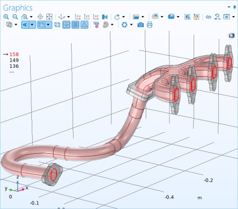
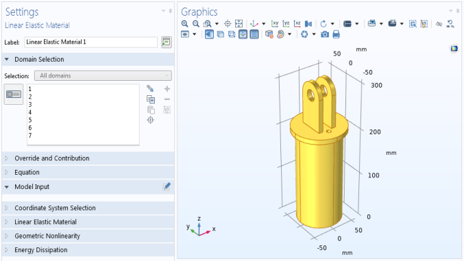
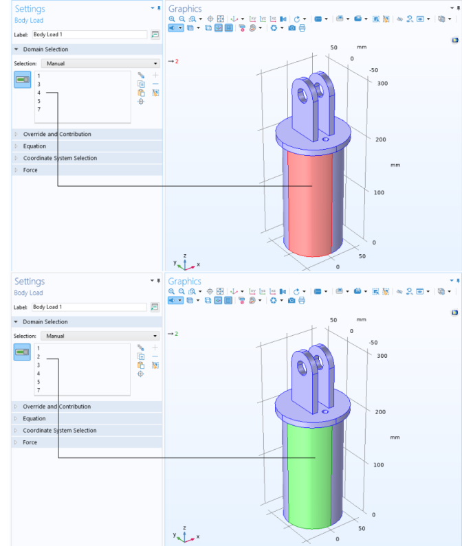
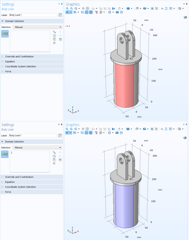
The Graphics window in the COMSOL Desktop highlights geometric entities at different stages of selection. A geometric entity is highlighted in red, blue, green, yellow, or with no highlight (gray) to indicate its status.
When assigning geometric entities to a node and you hover over that entity in the Graphics window, click once to add it to a selection list. See Figure 6-6 for an example. If you select the
Require click in Graphics window to activate hovering check box on the
Selections page under
Graphics>Interaction in the
Preferences dialog box, then you must first click once in the Graphics window before you can hover and click to select. See also
Selection Colors below.
When Group by Continuous Tangent is active, all boundaries or edges with continuous tangent are highlighted when hovering over one entity, as shown in
Figure 6-3. Clicking to select will add all the highlighted entities to a selection list.

Depending on the selection mode, the number of the selected geometric entity or the name of the selected geometry object appears in the top-left corner of the Graphics window. For boundaries in 3D geometries, the display also shows Up or
Down, depending on the side of the boundary that is selected to indicate the surface normal direction. The normal vector has “positive” and “negative” directions, referred to as the up and down directions, respectively. If you do not want to include that display, clear the
Show information on hover check box on the
Hovering page under
Graphics>Interaction page in the
Preferences dialog box.
You can also control the highlighting when hovering. By default, you get a full glow effect when highlighting an object such as a boundary. You can change this behavior on the Hovering page under
Graphics>Interaction page in the
Preferences dialog box. From the
Primary hover effect type list, choose
Full glow effect (the default),
Only glow lines,
No glow, or
Only lines. The lines options only highlight the bounding edges of boundaries in 3D, for example.
Hovering over or selecting selected geometric entities. When you hover over a geometric entity that has already been added to a selection, or if you select such a geometric entity in the Selection List window (indicated by
(selected) next to the entity number), it displays in green to indicate that it is included in the selection list. The same display of geometric entities or geometry objects as for the hovering over unselected geometry entities is available here. See
Figure 6-5 for an example.
Next to the Settings window’s selection list, there is an
Activate Selection button to toggle between turning on

and off

selections for that feature node’s selection list; that is, making the selections active for that selection list.
When the button is turned off, the selection mode is a preselection that is used for a selection that you add to the model by right-clicking in the
Graphics window (see
Right-Clicking to Select Geometric Entities and Add Physics Features) or from the toolbar, and the selection for the current node in the model tree is highlighted in yellow in the
Graphics window. See
Figure 6-4.


