 ) plot to represent and plot a frequency response in frequency bands. An octave band plot corresponds to plotting the average or integrated value of, for example, the squared pressure over a given frequency band defined by the center frequency or midfrequency and the bandwidth. What the plot shows is a “white noise transfer function” of the system; that is, it assumes that the input is of the same nature as the output. The data input to an octave band plot is a frequency-domain solution; for example, it can be the acoustic pressure resulting from a Frequency Domain study or a parametric frequency sweep. To add this plot type, right-click a 1D Plot Group node and choose Octave Band from the More Plots submenu. Right-click an Octave Band node to add a Graph Marker subnode if desired.
) plot to represent and plot a frequency response in frequency bands. An octave band plot corresponds to plotting the average or integrated value of, for example, the squared pressure over a given frequency band defined by the center frequency or midfrequency and the bandwidth. What the plot shows is a “white noise transfer function” of the system; that is, it assumes that the input is of the same nature as the output. The data input to an octave band plot is a frequency-domain solution; for example, it can be the acoustic pressure resulting from a Frequency Domain study or a parametric frequency sweep. To add this plot type, right-click a 1D Plot Group node and choose Octave Band from the More Plots submenu. Right-click an Octave Band node to add a Graph Marker subnode if desired.| For examples that use an Octave Band plot, see Absorptive Muffler: Application Library path Acoustics_Module/Automotive/absorptive_muffler and The Brüel & Kjær 4134 Condenser Microphone: Application Library path Acoustics_Module/Electroacoustic_Transducers/bk_4134_microphone. | 
| • |  Pressure (the default), to compute the octave plot treating the expression as an pressure prms. The input is the value p (it is generally a complex-valued variable). It is in turn used to calculate the rms pressure prms, which defines the level L: | 
 ) to pick a pressure reference from a list of predefined expressions.
) to pick a pressure reference from a list of predefined expressions.| • | 
 ) to pick a power reference from a list of predefined expressions.
) to pick a power reference from a list of predefined expressions.| • | 
 ) to pick a level reference from a list of predefined expressions.
) to pick a level reference from a list of predefined expressions.| • | 1/3 octave bands, to plot the response using 1/3 octave bands. | 
| • | 1/6 octave bands, to plot the response using 1/6 octave bands. | 
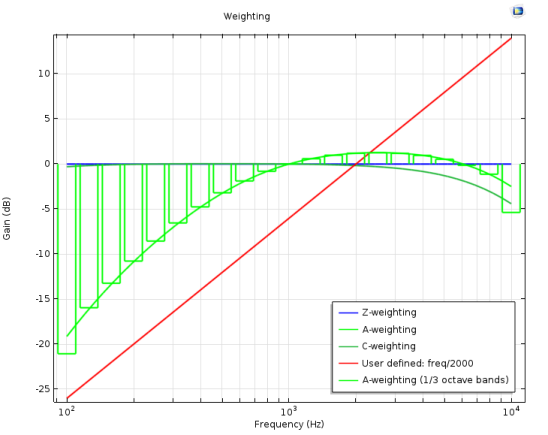
| The predefined weightings are defined in IEC 61672-1. See IEC 61672-1 Electroacoustics - Sound level meters - Part 1: Specifications for details. | 
| • | Z-weighted (flat) (the default), to use a zero weighting; that is, a flat weighting. | 
| • | A-weighted, to use a weighting that mimics the loudness perceived by the human ear. | 
| • | C-weighted, to use a C-weighting, which is an alternative standardized weighting that is in use within the acoustics community. | 
| • | Expression, to enter a user-defined value or expression for the weighting in the Expression field. The expression defines the gain as a function of the frequency. The gain given in dB is then given as 20·log10(expression). Use the frequency variable freq for user-defined expressions. | 
| • | Select Bar (the default) to display filled bars. Then select the color for the bars from the Color list. Choose Custom to select a custom color from the color palette that appears. | 
| • | Select Outline to display outlines of the bars. You can then specify settings for the line style and line markers for the outlines. | 
| • | Select Line to display a graph connecting the centerpoints of the bands. You can then specify settings for the line style and line markers for the graph. |