Use a Centroid Measurement (

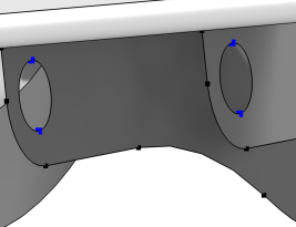
) node to measure the coordinates of a point or the average position of a selection of points, shown in
Figure 7-7. It generates parameters for the measured coordinates that can be used in subsequent nodes in the geometry sequence or when setting up the physics, which is useful when running a parametric sweep changing dimensions in the geometry. The resulting coordinates also appear in the
Parameter Values section.
To add a Centroid Measurement node, optionally select points in the Graphics window, then choose one of the following:
Click the Active button to toggle between turning ON

and OFF

the
Vertices selection. Select the points (vertices) that you want to measure in the Graphics window. They then appear in the
Vertices selection. If the geometry sequence includes user-defined selections above the
Centroid Measurement node, choose one of the selection nodes from the list next to
Vertices.