Start by adding a Layered Material at the
Materials node under
Global Definitions. Then, take the following steps to define the laminate:
All the layers are assumed in a continuity state. Optionally, in order to model a very thin layer of material, for example a glue layer between the two material layers, a material can be added in Interface Properties section. If an interface material is defined, you can create a discontinuity between two layers and use the interface material properties. To do this, add a
Delamination or
Thin Elastic Layer, Interface node in the Layered Shell interface. All interfaces selected in that node should have a material assignment, but there is no need to assign a material to interfaces which are not affected by such special features.
You can do that by creating Layer Cross Section Preview (
) and
Layer Stack Preview (
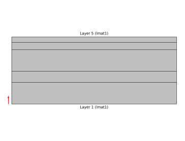
) plots. An example of a layer cross section plot showing a 2D cross section of a laminate having is shown in
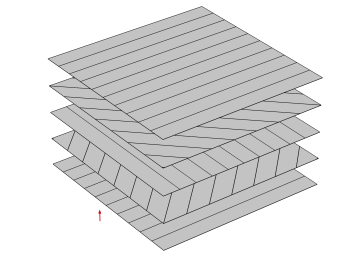
Figure 3-7. The thickness of each layer is visible. An example of a layer stack preview plot showing the stacking sequence is shown in
Figure 3-8.
You can also create the two preview plots under Results section using
Create Layer Cross Section Plot and
Create Layer Stack Plot buttons respectively. This helps in storing the preview plots in the model and also allows them to be available in an application, built on top of the model.