You are viewing the documentation for an older COMSOL version. The latest version is
available here
.
Setting Up a Rotating Machinery Model
The Rotating Machinery, Fluid Flow interfaces primarily handle two types of geometries with rotating parts.
The first type is where the whole geometry rotates. Typical examples are individual parts in turbomachinery and lab-on-a-chip devices. For such cases, the selection for the Rotating Domain under the Definitions node should be all domains in the geometry.
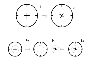
The other type is geometries where it is possible to divide the modeled device into rotationally invariant geometries. The operation can be, for example, to rotate an impeller in a baffled tank, as in
Figure 3-9
where the impeller rotates from position 1 to 2.
The first step to set up these type of models is to divide the geometry into two parts, as shown in Step 1a. Draw the geometry using separate domains for fixed and rotating parts. If you intend to do a time-dependent simulation, activate the assembly (using an assembly instead of a union, see
Geometry Modeling and CAD Tools
in the
COMSOL Multiphysics Reference Manual
) and create identity pairs, which makes it possible to treat the domains as separate parts in an assembly.
The second step is to remove the nonrotating domains from the Rotating Domain selection (Step 1b).
Once this is done, proceed to the usual steps of setting the fluid properties, boundary conditions. Apply a Flow Continuity to assembly pairs (Step 2a). Then mesh and solve the problem.
Figure 3-9:
The modeling procedure in the Rotating Machinery, Fluid Flow interface.