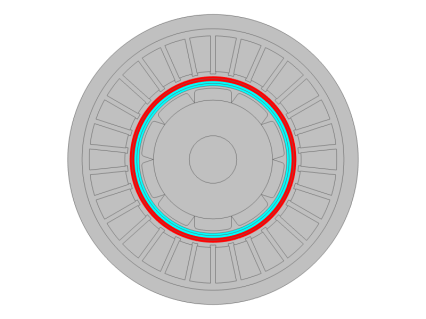
In Figure 5-6 and
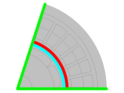
Figure 5-7 it is shown how typical conditions should be set for a rotating machine where either the full machine or a sector is drawn in the geometry. For the sake of simplicity, a synchronous machine with an external stator and an internal rotor with 10 poles is used in this example. Furthermore, the stator configuration is such that the minimal sector corresponds to one fifth of the whole geometry.
If a sector of the whole machine is drawn, a Rotational Periodicity node should also be added with a selection corresponding to the green line in
Figure 5-7.
When modeling a single sector, it is important to specify if the symmetry is periodic or antiperiodic. If the Rotational periodicity type is set to
From physics, this is done by specifying the
Number of poles in the
Motion Settings section at the physics level. If the number of poles is an even multiple of the detected number of sectors, continuity is assumed. Conversely, if the number of poles is an odd multiple of the detected number of sectors, antiperiodicity is going to be assumed. The number of detected sectors is displayed along with the type of periodicity in the bottom of the
Motion Settings section. The default value of the number of poles is zero, which results in periodicity being assumed.
The button Add Rotational Boundary Features in the
Motion Settings section automatically adds one
Rotational Continuity Pair node for each pair that is geometrically consistent with two circular sliding objects. It also adds the corresponding
Rotational Continuity Pair node if a single sector is drawn.