Impedance Boundary Condition
The Impedance Boundary Condition
is used at boundaries where the field is known to penetrate only a short distance outside the boundary. This penetration is approximated by a boundary condition to avoid the need to include another domain in the model. Although the equation is identical to the one in the low-reflecting boundary condition, it has a different interpretation. The material properties are for the domain outside the boundary and not inside, as for low-reflecting boundaries. A requirement for this boundary condition to be a valid approximation is that the magnitude of the complex refractive index
where μ1 and ε1 are the material properties of the inner domain, is large; that is, | N | >> 1.
When used with the Electromagnetic Waves, Beam Envelopes interface, the propagation direction in the exterior layer can be specified. Setting the propagation direction to be in the normal direction is the default option and results in the behavior as described above. However, setting the propagation direction to be given by the wave vector direction takes the tangential wave vector components from the Wave Vectors settings for the physics and the longitudinal component is derived to make the wave number satisfy the wave number for the exterior layer. This option is useful if the exterior domain is a dielectric material.
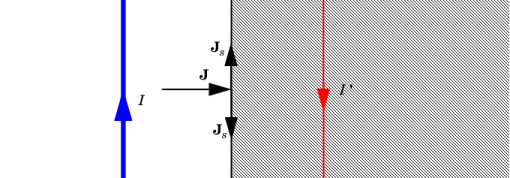
The source electric field Es can be used to specify a source surface current on the boundary.
Figure 3-5: The impedance boundary condition is used on exterior boundaries representing the surface of a lossy domain. The shaded (lossy) region is not part of the model. The effective induced image currents are of reduced magnitude due to losses. Any current flowing into the boundary is perfectly balanced by induced surface currents as for the perfect electric conductor boundary condition. The tangential electric field is generally small but nonzero at the boundary.
Propagation Direction
This section is only available for the Electromagnetic Waves, Beam Envelopes interface. Select a Propagation directionNormal direction (the default) or From wave vector. The Normal direction option assumes that the wave in the exterior material propagates essentially in the normal direction, whereas the From wave vector option assumes that the tangential wave vector component is continuous at the boundary, as specified by the wave vectors k1 and k2 for the Electromagnetic Waves, Beam Envelopes interface. The normal component for the wave vector in the exterior material is obtained from the wave number, given the material parameters of the exterior domain. Thus, this option implements Snell’s law of refraction at the boundary, which makes this option useful also for dielectric exterior materials.
Impedance Boundary Condition
Select an Electric displacement field modelRelative permittivity, Refractive index (the default), Loss tangent, loss angle, Loss tangent, dissipation factor, Dielectric loss, Drude-Lorentz dispersion model, Debye dispersion model, or Sellmeier dispersion model. See the Wave Equation, Electric node, Electric Displacement Field section, for all settings.
Source Electric Field
To display this section, click the Show More Options button () and select Advanced Physics Options in the Show More Options dialog box.
Enter a Source electric field Es (SI unit: V/m). The default is 0 V/m.
See Skin Depth Calculator to evaluate the skin depth of a homogeneous material.
Fresnel Equations: Application Library path Wave_Optics_Module/Verification_Examples/fresnel_equations