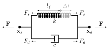
The Spring-Damper node is used to define elastic and dissipative forces between a source and a destination attachment. Two different spring types are available. When using the
directional spring (
Figure 3-32), all forces act in the direction of the spring extension. With the
matrix spring formulation, more general dependencies between the displacements and forces can be defined.
where Xs and
Xd are the original positions of the two points, and
us and
ud are their respective displacements. For the special case where the source point is selected as a fixed point,
Specify an initial spring extension Δl0 in addition to the initial geometrical distance between the two points, so that the free length of the spring is
It is also possible to specify the free length of the spring explicitly. The spring extension Δl is then computed as the difference between the current spring length and the free length
lf,
where Θs and
Θd are the rotations of the source and destination attachments, respectively. In case of geometrically nonlinear studies, the relative rotation vector is instead computed from the quaternion multiplication,
where qs and
qd are the source and destination rotations represented by unit quaternions, and
Δq is a quaternion representing the differential rotation, which can be converted to an axis-angle representation defining the relative rotation vector.
If the check box Include rotational contribution in displacement in the
Spring-Damper section is selected, an additional term is included in the relative displacement vector which can be interpreted as the displacement at the tip of a bar element which connects the source and destination due to the rotation at the destination point. In a geometrically linear study, the relative displacement is then defined as
If k depends on the extension, so that the spring is nonlinear, it should be interpreted as a secant stiffness, that is
where c is the viscous damping coefficient.
When choosing the matrix formulation, the spring and the damper forces are computed from the relative displacements and rotations. In the most general case, the spring-damper force,
F, and the spring-damper moment,
M, are
where the subscripts s and
d refer to the spring and damper, respectively; the different
k and
c represent sub-matrices of size 3x3, describing the elastic and the dissipative forces and moments. In 2D, some of the matrices related to the rotation and to the translational-rotational coupling have components which are zero by definition.
In a time-dependent analysis, the energy dissipated in the damper, Wd, is computed using an extra degree of freedom. The following equation is added:
If instead the matrix formulation is used, the elastic energy in the spring is
In a time-dependent analysis, the energy dissipated in the damper, Wd, is computed using an extra degree of freedom. The following equation is added: