Use the Thickness and Offset node to define the thickness for the different parts of a shell or membrane structure. In addition to the default
Thickness and Offset node always present in the interface, you can add more
Thickness and Offset nodes if needed.
Enter a value for the Thickness d0 of the selected boundaries. The default is 0.01 m in the Shell and Plate interfaces, and 0.0001 m in the Membrane interface. If an expression is used, the thickness can be variable so that a tapered shell or membrane can be modeled.
You can also add a Thickness Change subnode to take into account that the thickness may change over time.
For User defined, enter a value or expression in the
zrel_offset field for the offset. It is given as the ratio between the offset distance and half the thickness. A value of +1 means that the actual bottom surface is located on the meshed boundary, and a value of
−1 means that the top surface is located on the meshed boundary.
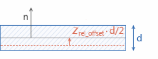
Values of zrel_offset outside the range [-1,1] are also allowed.