Use the Bend subnode to account for a local stiffness reduction and a local stress increase in a bent pipe. Curved pipe segments with a circular cross section tend to ovalize when loaded in bending. This three-dimensional effect cannot be resolved with classical beam theory, but it may have a significant effect on flexibility and stress results. It is therefore common practice to reduce the pipe stiffness in a bend with so-called
flexibility factors. Similarly, to account for the stress increase due to shape changes of the cross section so-called
stress intensification factors (SIFs) are applied. Both flexibility factors and SIFs often depend on geometric properties of the pipe such as the bend radius, mean wall radius, and the wall thickness. Sometimes also the internal pressure is accounted for, which tends to counteract the ovalization.
The Bend feature assumes that the bend is modeled with a circular arc. The local y direction of the bend points in the direction of the curvature vector; that is, bending about the y-axis is defined as out-of-plane bending, and bending about the z-axis is defined as in-plane bending. Since
Bend defines its own coordinate system, it overrides the
Section Orientation node.
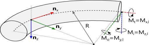
In the Bend feature enter one or more of the following correction factors:
The flexibility factors do not directly reduce the stiffness properties, such as the moment of inertia Iyy and
Izz, as this would affect the stress evaluation as well. Instead, the stiffness reduction is effectively performed when assembling the global stiffness matrix, where the element matrices of bent sections use reduced stiffness properties.
Physics tab with Pipe Cross Section node selected in the model tree: