Solid Mechanics
The Solid Mechanics interface offers the most general modeling of structural mechanics problems and is based on general principles of continuum mechanics. It is the interface which contains the largest number of material models, and the most advanced boundary conditions.
The drawback with using solid elements is that the models can become computationally expensive, especially in 3D. For structures which are thin or slender, you should consider using one of the specialized physics interfaces.
3D Solid Geometry
The degrees of freedom (dependent variables) in 3D are the global displacements u, v, and w in the global x, y, and z directions, respectively.
Figure 2-1: Loads and constraints applied to a 3D solid using the Solid Mechanics interface.
2D Geometry
Plane Stress
The plane stress variant of the 2D physics interface is useful for analyzing thin in-plane loaded plates. For a state of plane stress, the out-of-plane components of the stress tensor are zero.
Figure 2-2: Plane stress is used to model plates where the loads are only in the plane; it does not include any out-of-plane stress components.
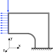
The 2D physics interface for plane stress allows loads in the x and y directions, and assumes that these are constant throughout the material’s thickness, which can vary with x and y. The plane stress condition prevails in a thin (compared to the in-plane dimensions) flat plate in the xy-plane loaded only in its own plane and without any z direction restraint.
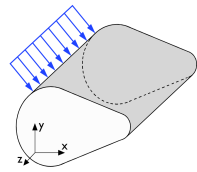
Plane Strain
The plane strain variant of the 2D physics interface that assumes that all out-of-plane strain components of the total strain tensor εz, εyz, and εxz are zero.
Figure 2-3: A geometry suitable for plane strain analysis.
Loads in the x and y directions are allowed. The loads are assumed to be constant throughout the thickness of the material, but the thickness can vary with x and y. Formally, the plane strain condition requires that the ends of the object are constrained in the z direction, but it is often also used for central parts of an object that is long in the z direction (compared to the in-plane dimensions). One example is a long tunnel along the z-axis where it is sufficient to study a unit-depth slice in the xy-plane.
Generalized Plane Strain
Generalized plane strain is similar to plane strain in the sense that transverse stresses can develop in the 2D cross section of a long object. The requirement that the out-of-plane strain is zero, is however relaxed. Instead, an assumption about zero resulting force in the transverse direction is used. Optionally, assumptions about zero bending moments over the cross section can be added. Generalized plane strain conditions prevail in the in the inner parts of a long object with free ends. For many cases, generalized plane strain conditions is the 2D approximation that is closest to a full 3D solution.
Axisymmetric Geometry
The axisymmetric variant of the Solid Mechanics interface uses cylindrical coordinates r,  (phi), and z. All properties are independent of the azimuthal angle .
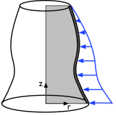
In the default version of the interface, displacements occur only in the r-z plane, and there are two degrees of freedom, u and w. By selecting the Include circumferential displacement option, you can model also torsion around the axis of rotational symmetry. The azimuthal rotation degree of freedom v is then included. In addition, many features, such as load features, allow values to be entered in the  direction.
The 2D axisymmetric geometry is viewed as the intersection between the original axially symmetric 3D solid and the half plane  = 0, r ≥ 0. Therefore, the geometry is drawn only in the half plane r ≥ 0, and it recovers the original 3D solid by rotating the 2D geometry about the z-axis.
Figure 2-4: Rotating a 2D geometry to recover a 3D solid.
Axisymmetric Twist and Bending: Application Library path Structural_Mechanics_Module/Verification_Examples/axisymmetric_twist_and_bending